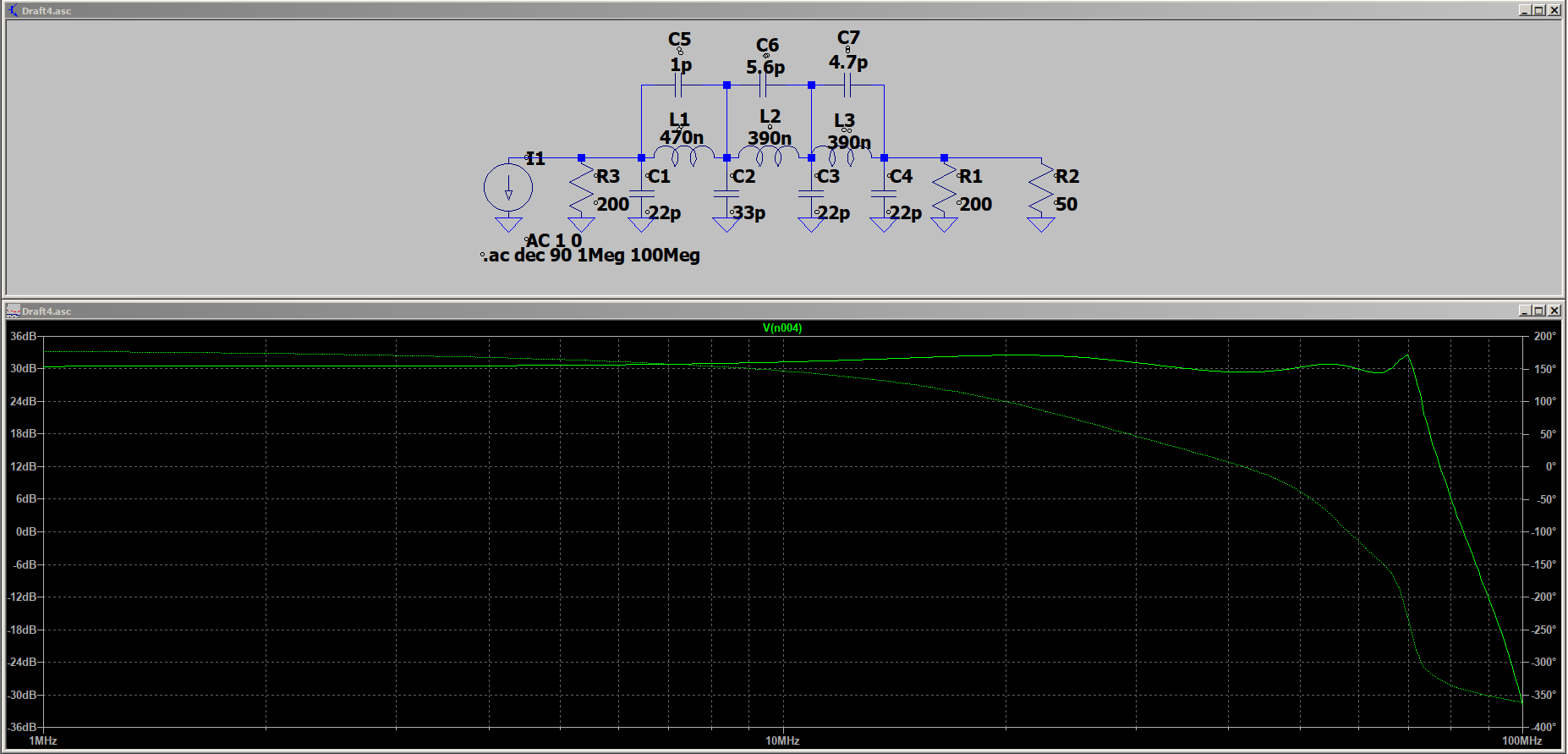
In order to simulate a radio transmitter using the AD9850 module, I created a model for the output of this module. The primary sine wave output is filtered by a low-pass filter which cuts off harmonics above 100Mhz:
However, this filter is not present on the complimentary output of the module. Thus, I modeled the module's sine wave outputs with the following schematic:
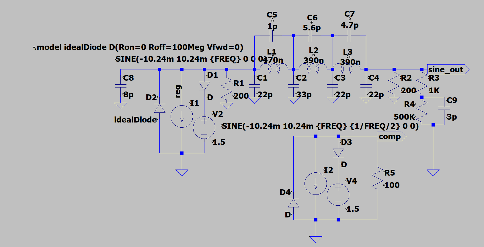
The current source is modeled with voltage sources and ideal diodes in parallel to set a maximum and minimum voltage compliance output, a handy trick I learned from a Youtube video.
It will be interesting to see how closely this actually models the device.