In Solar APRS Weather Station Published: 23 Jul 2023; Last edited: 23 Jul 2023 See just this article
ADS Lab 2: A Transmission Line and Lumped-Element Bandpass Filter
Introduction
As previously discussed, coupled microstrip filters can offer improved performance over filters comprised solely of lumped elements in some cases. Coupled-line microstrip filters are common at sufficiently high frequencies when the physical size can be very small. However, at VHF frequencies, traditional quarter-wavelength coupled lines can be too large for most applications. Additionally, having a smaller element size allows filters to have more elements (and a potentially much sharper cutoff) within the same size constraints.
Transmission Line and Lumped-Element Bandpass Filters
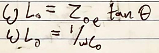
The behavior of a diagonally-shorted quarter-wavelength pair of coupled lines can be approximated with an arbitrary-length transmission line with lumped elements on either side [1]. This has the effect of better rejection outside of the passband, reducing transmission at some of the harmonics of the passband [1]. To determine the values of the lumped elements (a shunt capacitor and inductor on either side of the resulting transmission line), analysis of characteristic impedance can be used to relate the diagonally shorted coupled lines to the transmission line between lumped elements [1]. Kang and Xu simplified this relationship into the equations in Figure 1.
Figure 1: Kang and Xu's equations to determine lumped elements to accompany a transmission line replacing diagonally shorted coupled lines [1]
To confirm this relationship, variables in ADS were created based on these equations (Figure 2), and the simplified equivalent circuits were modeled with ideal components (Figure 3).
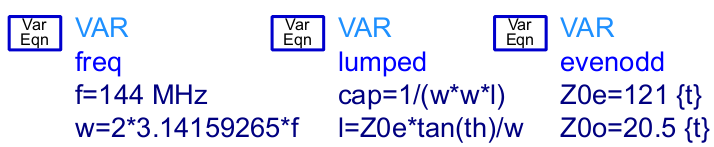
Figure 2: Variables in ADS for calculating the lumped element values
In Figure 2, above, "freq" defines the center frequency traditionally and in angular units, "cap" is the capacitance of the shunt capacitor on either end of the transmission line, "l" is the inductance of the shunt inductor on either side of the transmission line, "Z0e" and "Z0o" are the even and odd-characteristic impedances of the coupled lines, and "th" is the electrical length of the arbitrary-length transmission line, in radians.
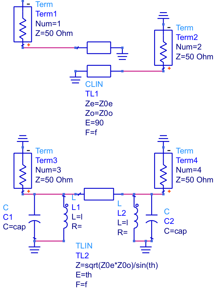
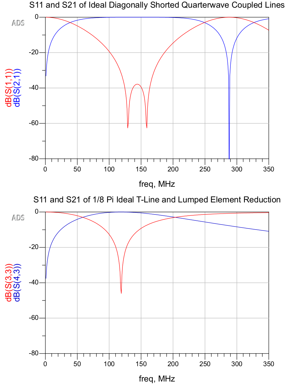
Figure 3: Coupled lines and transmission line with ideal lumped elementsFigure 4: Return loss and insertion loss of both circuits, simulated with ideal components
As is evident in Figure 4, the reduced transmission line circuit exhibits very similar characteristics as a bandpass filter. The primary discrepancies are that the harmonic passbands are attenuated, and, due to the resonant LCs, the return loss becomes unimodal and the passband becomes slightly narrower.
Such a filter could benefit from sharper rolloff from more elements, and should be simulated with non-ideal components. To facilitate the design process by the equations in Figure 1, I created the spreadsheet embedded below:
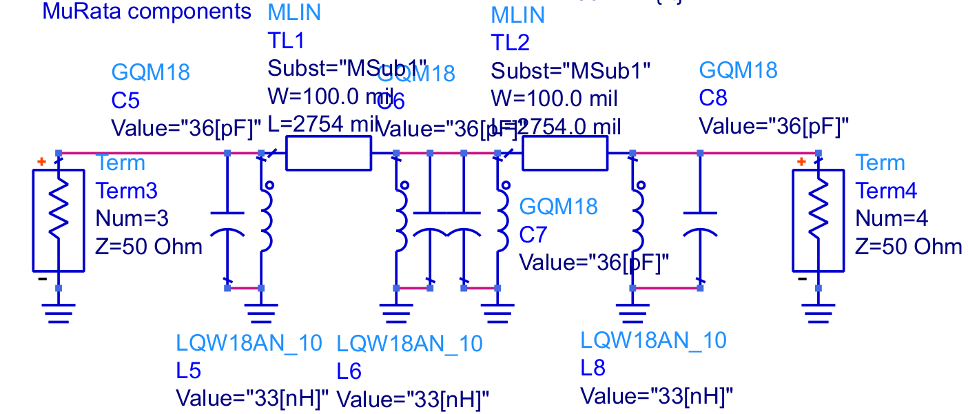
This is used to calculate the lumped elements on either side of a transmission line with a given electrical length to replace a diagonally-shorted pair of coupled lines with given even and odd characteristics at a given center frequency. In this specific case, a 144MHz bandpass filter with 0.5dB ripple (as discussed previously) comprised of two pairs of π/2 coupled lines is replaced by a pair of π/8 transmission lines with lumped elements. The closest actual values for the capacitors and inductors are 36pF and 33nH, respectively. For the models, I chose parts from the MuRata GQM and LQW series, using their design kit. Figure 5 shows the schematic of the resulting transmission line filter. Linecalc is used to calculate the physical characteristics of the transmission line segments.
Figure 5: Two-stage transmission line and lumped element filter with MuRata parts
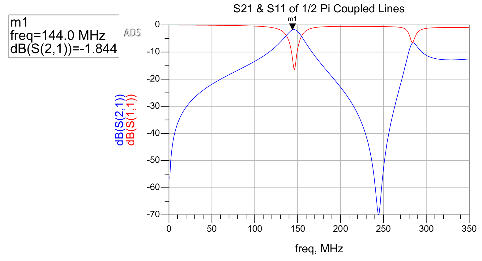
This circuit is then simulated in ADS. The behavior of the original coupled line filter is shown in Figure 6, and that of the reduced-size transmission line and lumped element filter is shown in Figure 7.
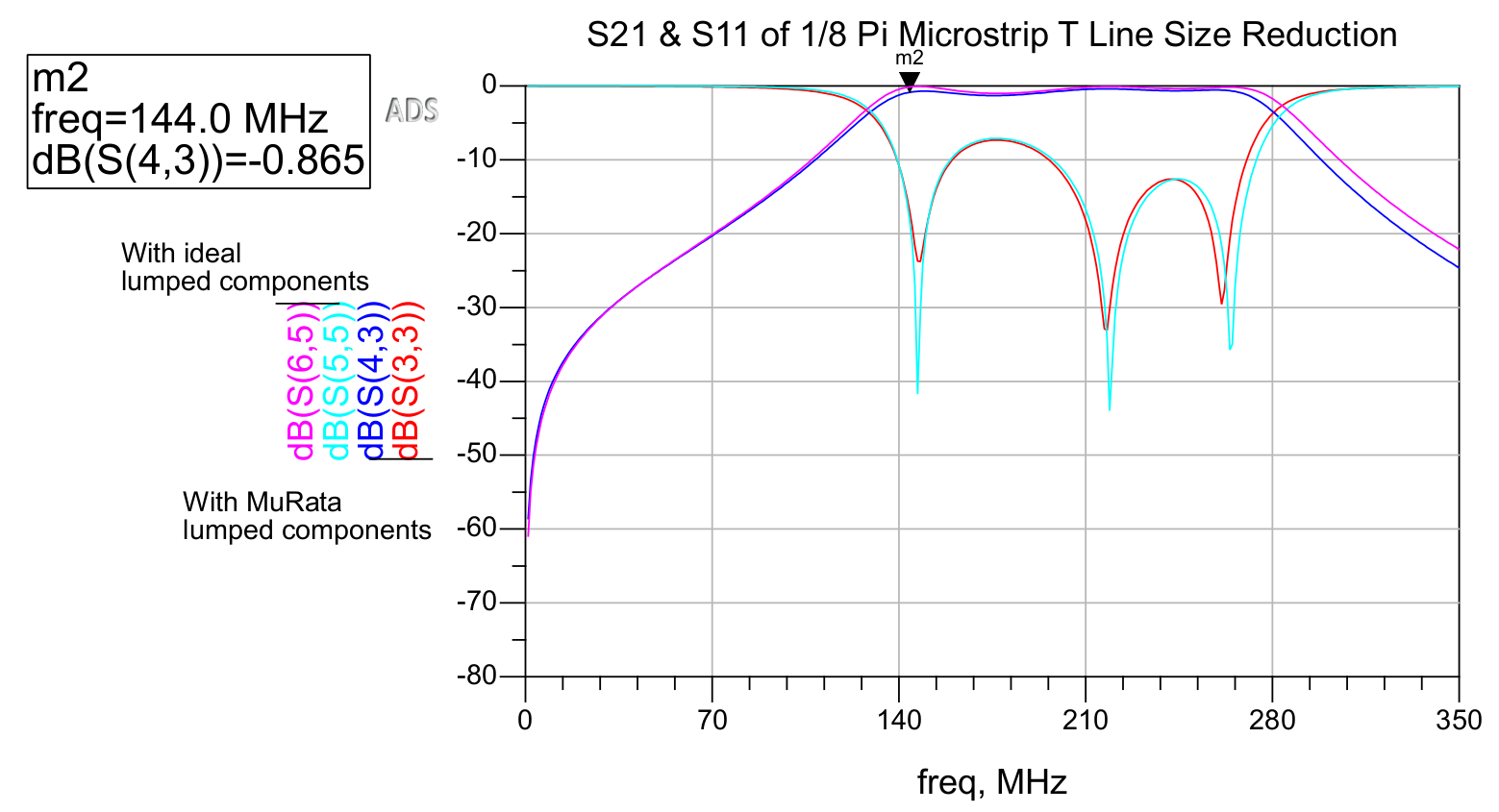
Figure 6: Insertion loss and return loss of a two-stage 144MHz coupled line bandpass filterFigure 7: Insertion loss and return loss of transmission line and lumped element equivalent filter, with ideal and MuRata lumped components
As is evident in Figure 7, the effects of using non-ideal lumped components are minimal, as opposed to the effects of non-ideal components in filters that make use of only lumped components. Transmission line filters with lumped components can be advantageous in attaining both a favorable match (due to resonance) as well as a low insertion loss in the passband.
Interestingly, the resulting passband is far wider in the transmission line filter. This could likely be remedied by adding more elements and through further tuning, or by investigating the cascaded impact of the fractional bandwidth used to derive the even and odd characteristics of the original coupled line filter. It is also possible that resonant characteristics of the transmission lines produces this effect.
As far as size reduction, each of the two coupled line pairs in the original filter is approximately 11.3 inches in length, while the transmission line segments in the new filter are only about 2.8 inches, and could be reduced further. Although the length of the transmission lines in the resulting filter can theoretically be arbitrarily defined, performance is impacted when this value becomes excessively small.
This approach for designing VHF bandpass filters is convenient in allowing the low-insertion loss of transmission line filters to be achieved in the small footprint of lumped-element filters, while also obtaining the favorable return loss and tight passband that resonant LC circuits can provide.
[2] M, Abhinaya, B, B., Dashora, H., & Kumar, J. (2020). Design and implementation of coupled line bandpass filter at c-band. AIJR Preprints. https://doi.org/10.21467/preprints.232
In Solar APRS Weather Station Published: 23 Jul 2023; Last edited: 23 Jul 2023 See just this article
My arduino-controlled AD9850-based APRS transmitter is one application that requires small and low-loss VHF filters. More specifically, a sharp-cutoff bandpass filter is required to reduce mixing products and harmonics thereof below the legal limit. The initial approach was to use a 5th order LC Chebyshev bandpass filter.
Prior to using Keysight's Pathwave ADS, this filter was simulated in LTSpice with ideal components. Ideal components result in the filter working perfectly, but success with this design was practically far more challenging as a result of the nonexistence of ideal components. As documented in a previous post, the sharp-cutoff LC bandpass filter performed too poorly in the real world than could be useful, with a measured insertion loss of nearly 20dB in the passband.
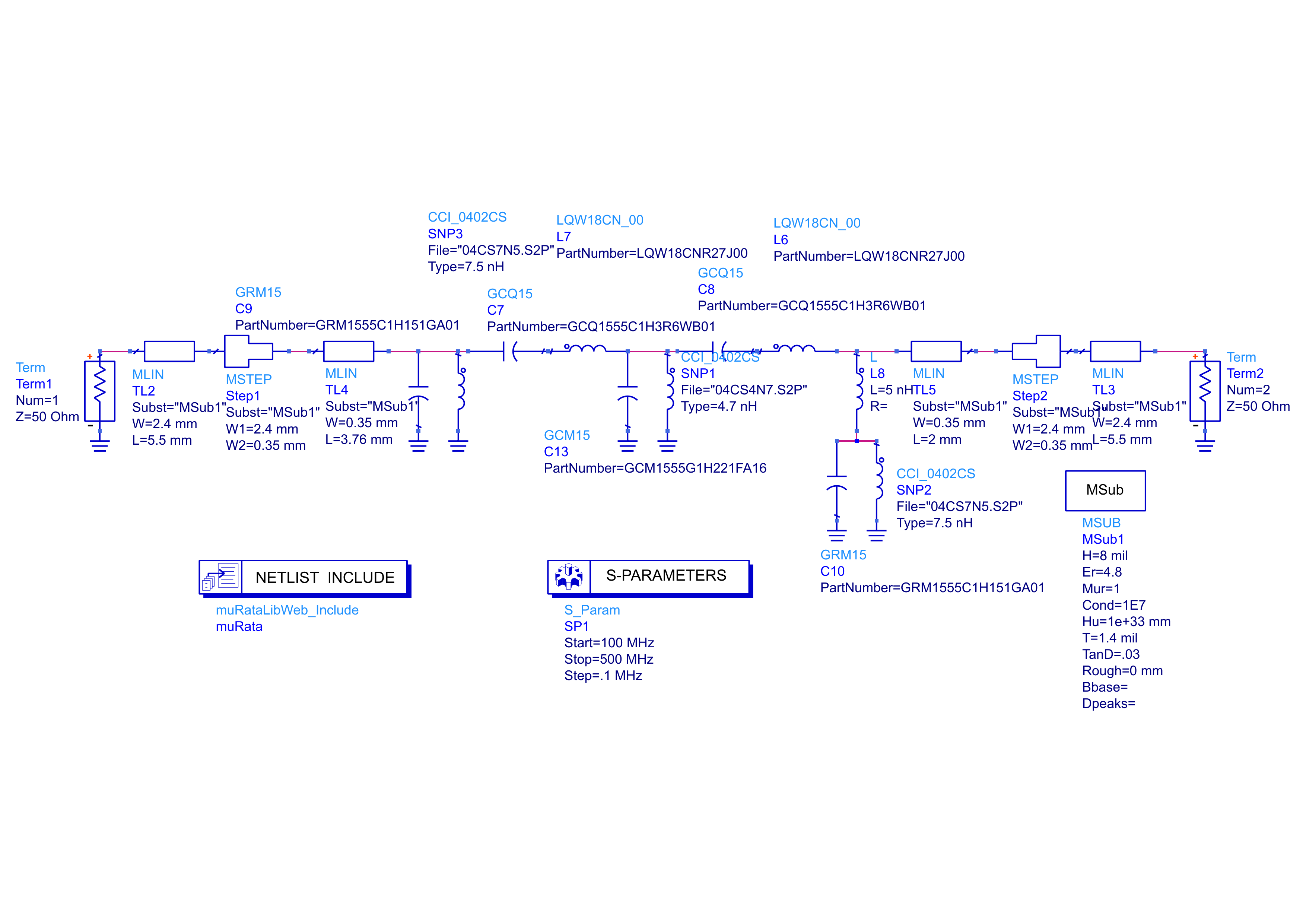
The first step after measuring unexpectedly attenuated waveforms about this filter was to build the filter on an pull-out structure that I included on the transmitter board for further testing with an SMA connector at each of its two ports. Upon measuring this with a NanoVNA pocket vector network analyzer, the 20dB insertion loss was observed. To confirm the plausibility of these results (being wary of measurement or calibration error), I created an identical schematic to the pull-out structure with this filter in a new ADS schematic, using models from MuRata's design kit for the MuRata components used. I tried to approximately model the microstrip transmission line to the SMA connectors using MLIN and MSTEP components in ADS after creating an MSub block with the parameters of the PCBWay board. The schematic is shown in Figure 1:
Figure 1: Schematic and simulation setup for the original lumped-element bandpass filter
The NanoVNA was connected with the NanoVNASaver software to save a touchstone file for comparison with ADS's S-Parameter simulation. Results are displayed in Figure 2:
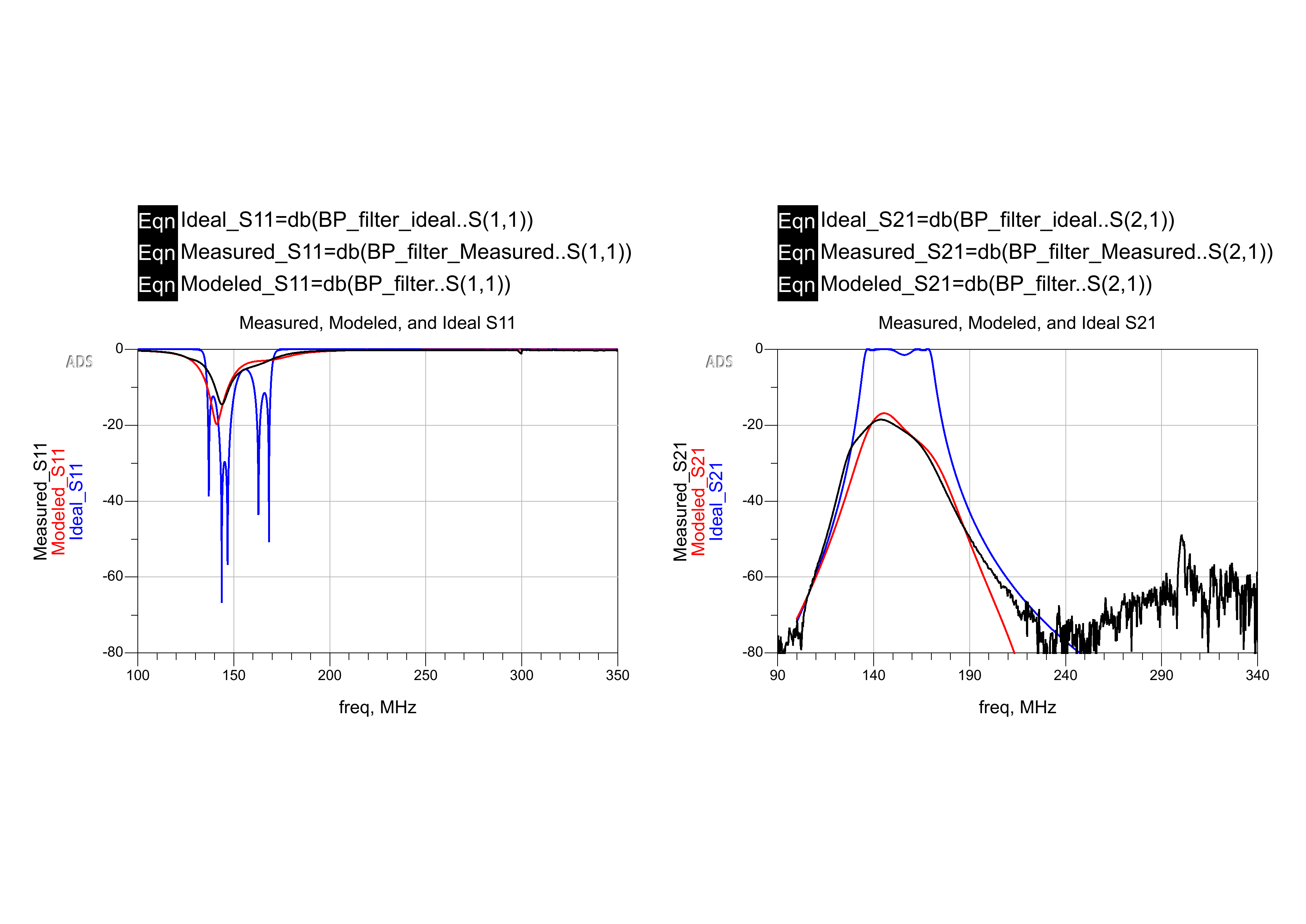
Figure 2: Measured vs. modeled with ideal and actual component models
The blue traces show what was initially expected, having initially simulated everything with ideal components. The red and black traces show what was modeled with actual component libraries in ADS and measured via the NanoVNA. Evidently, this bandpass filter is not usable for this application, as 20dB insertion loss in the passband removes far too much of the desired signal. While the return loss is very favorable in the 144MHz passband, the insertion loss in the passband is too significant. A different bandpass filter technology must be employed to combat this issue.
Parallel Coupled Lines as Chebyshev Bandpass Filters
Parallel quarter-wavelength coupled lines can be used to realize fairly low-loss bandpass filters with microstrip technology in some cases where LC filters might not be practical [1].
The elements of the bandpass filter can be treated as admittance inverters in order to derive coupled lines that take the place of the lumped elements [1].
Even and odd characteristics for parallel quarterwave coupled lines used to replace lumped elements in a symmetric chebyshev bandpass filter can be found by determining the characteristic admittances about each element [1, 3]. Even and odd characteristics for elements of a 0.5dB ripple chebyshev bandpass filter with a fractional bandwidth (3dB cutoff angular frequency delta over the center) of approximately 0.12 as calculated by Abhinaya et al. are listed in Table 1 [1].
Table 1: Even and odd characteristics of Chebyshev bandpass filter elements with 0.5dB ripple and Δ≈0.12 [1]
Element (1 through n)
Z0e (Ohms)
Z0o (Ohms)
1, n
72.025
38.929
2, n-1
57.282
44.382
3, n-2
55.844
45.274
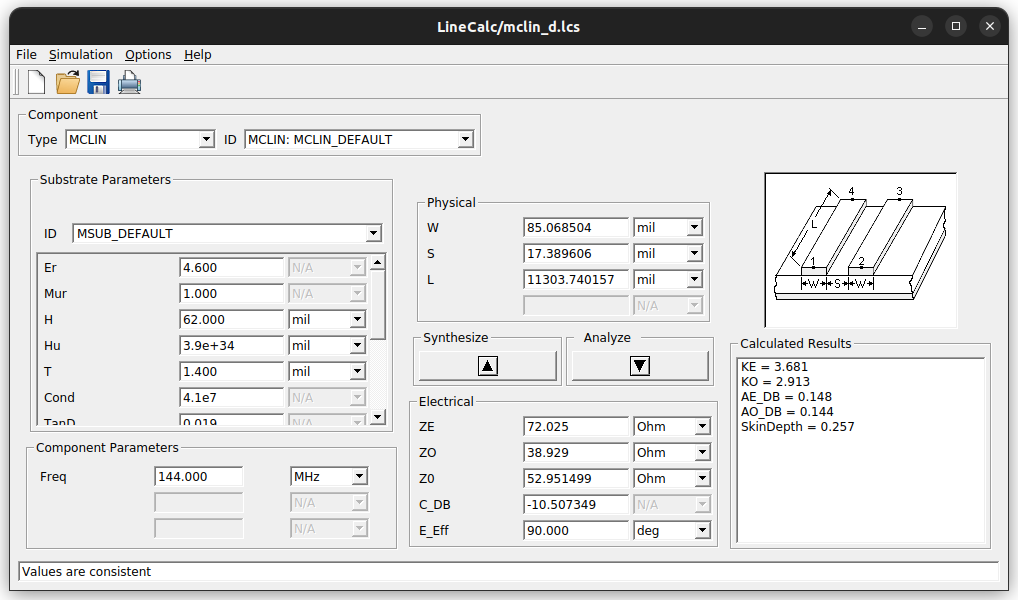
LineCalc is used to determine the physical parameters of microstrip coupled lines for a two-element bandpass filter about 144 MHz (see Figure 3). Both sets of coupled lines in this filter are identical, being the first and last (1, n in Table 1) elements in a symmetric filter. The substrate parameters used for the design of this filter are those from JLCPCB's capabilities from here on.
Figure 3: Linecalc to calculate physical parameters of coupled line microstrip
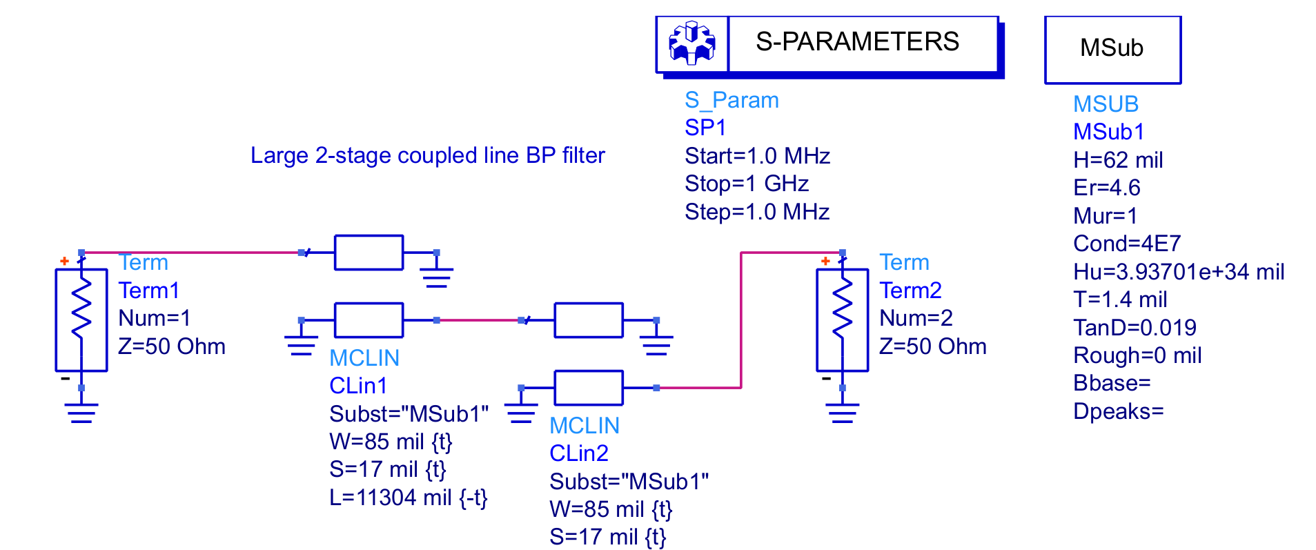
This is implemented in an ADS schematic (figure 4) as a pair of diagonally shorted coupled line pairs.
S parameter data from the simulation is shown in Figure 5.
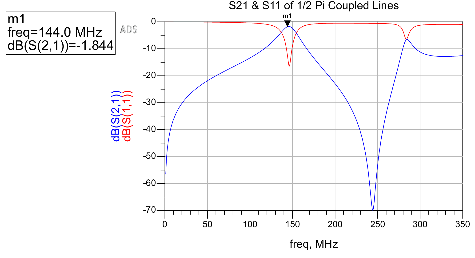
Figure 4: Schematic of the quarter-wave 144MHz coupled line bandpass filterFigure 5: Insertion loss and return loss of the simulated coupled line filter
As displayed in Figure 5, simulated insertion loss is far more acceptable than that of the original, lumped-element filter (shown in Figure 2). The rolloff is not nearly as steep, so for use in my transmitter design, more elements are required (more elements exist in the original, lumped-element filter). However, rejection of many of the mixing tones' harmonics around 250MHz is quite acceptable.
Each of these pairs of coupled lines is approximately 11.3 inches long. Because of this massive size at VHF frequencies, more elements might not be practical in most applications, including in my Arduino controlled APRS transmitter. Regardless, microstrip coupled line filters offer advantages over lumped-element equivalents in terms of loss and, depending upon size and constraints of PCB fabrication, potentially cost.
Simulation with non-ideal components and materials is extremely helpful in design of such devices because ideal components and materials cannot exist and often exhibit drastically different behavior in narrowband filters.
References
[1] M, Abhinaya, B, B., Dashora, H., & Kumar, J. (2020). Design and implementation of coupled line bandpass filter at c-band. AIJR Preprints. https://doi.org/10.21467/preprints.232
After almost 10 months, I am finally nearing the first production release of CubeServer, the software powering a school-wide engineering competition behind-the-scenes!