In Solar APRS Weather Station Published: 23 Jul 2023; Last edited: 23 Jul 2023 See just this article
ADS Lab 2: A Transmission Line and Lumped-Element Bandpass Filter
Introduction
As previously discussed, coupled microstrip filters can offer improved performance over filters comprised solely of lumped elements in some cases. Coupled-line microstrip filters are common at sufficiently high frequencies when the physical size can be very small. However, at VHF frequencies, traditional quarter-wavelength coupled lines can be too large for most applications. Additionally, having a smaller element size allows filters to have more elements (and a potentially much sharper cutoff) within the same size constraints.
Transmission Line and Lumped-Element Bandpass Filters
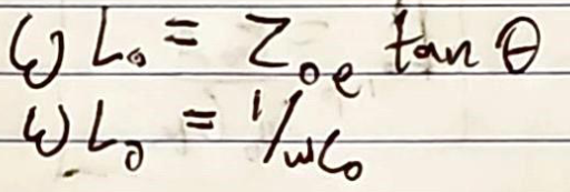
The behavior of a diagonally-shorted quarter-wavelength pair of coupled lines can be approximated with an arbitrary-length transmission line with lumped elements on either side [1]. This has the effect of better rejection outside of the passband, reducing transmission at some of the harmonics of the passband [1]. To determine the values of the lumped elements (a shunt capacitor and inductor on either side of the resulting transmission line), analysis of characteristic impedance can be used to relate the diagonally shorted coupled lines to the transmission line between lumped elements [1]. Kang and Xu simplified this relationship into the equations in Figure 1.
Figure 1: Kang and Xu's equations to determine lumped elements to accompany a transmission line replacing diagonally shorted coupled lines [1]
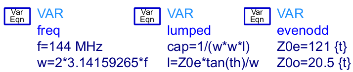
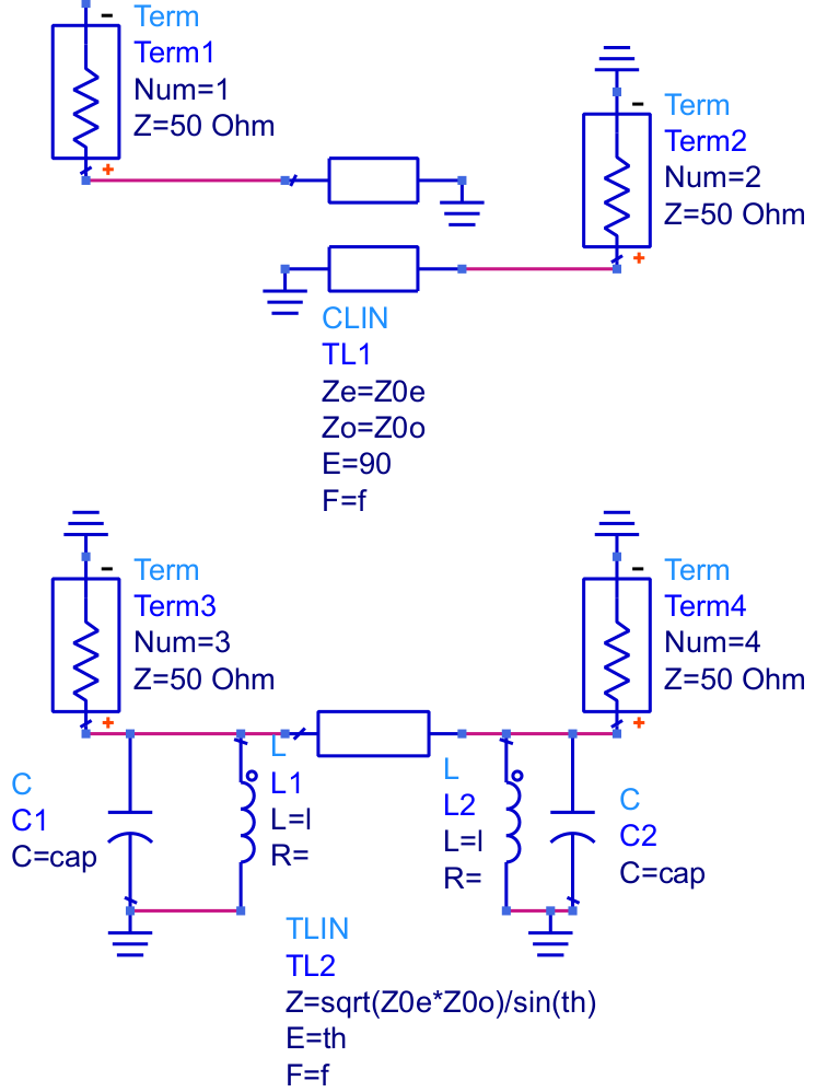
To confirm this relationship, variables in ADS were created based on these equations (Figure 2), and the simplified equivalent circuits were modeled with ideal components (Figure 3).
Figure 2: Variables in ADS for calculating the lumped element values
In Figure 2, above, "freq" defines the center frequency traditionally and in angular units, "cap" is the capacitance of the shunt capacitor on either end of the transmission line, "l" is the inductance of the shunt inductor on either side of the transmission line, "Z0e" and "Z0o" are the even and odd-characteristic impedances of the coupled lines, and "th" is the electrical length of the arbitrary-length transmission line, in radians.
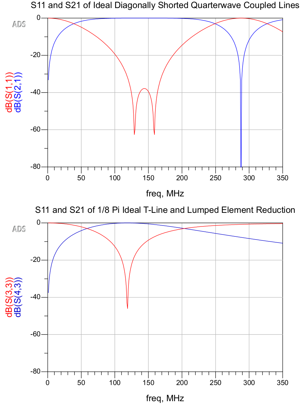
Figure 3: Coupled lines and transmission line with ideal lumped elementsFigure 4: Return loss and insertion loss of both circuits, simulated with ideal components
As is evident in Figure 4, the reduced transmission line circuit exhibits very similar characteristics as a bandpass filter. The primary discrepancies are that the harmonic passbands are attenuated, and, due to the resonant LCs, the return loss becomes unimodal and the passband becomes slightly narrower.
Such a filter could benefit from sharper rolloff from more elements, and should be simulated with non-ideal components. To facilitate the design process by the equations in Figure 1, I created the spreadsheet embedded below:
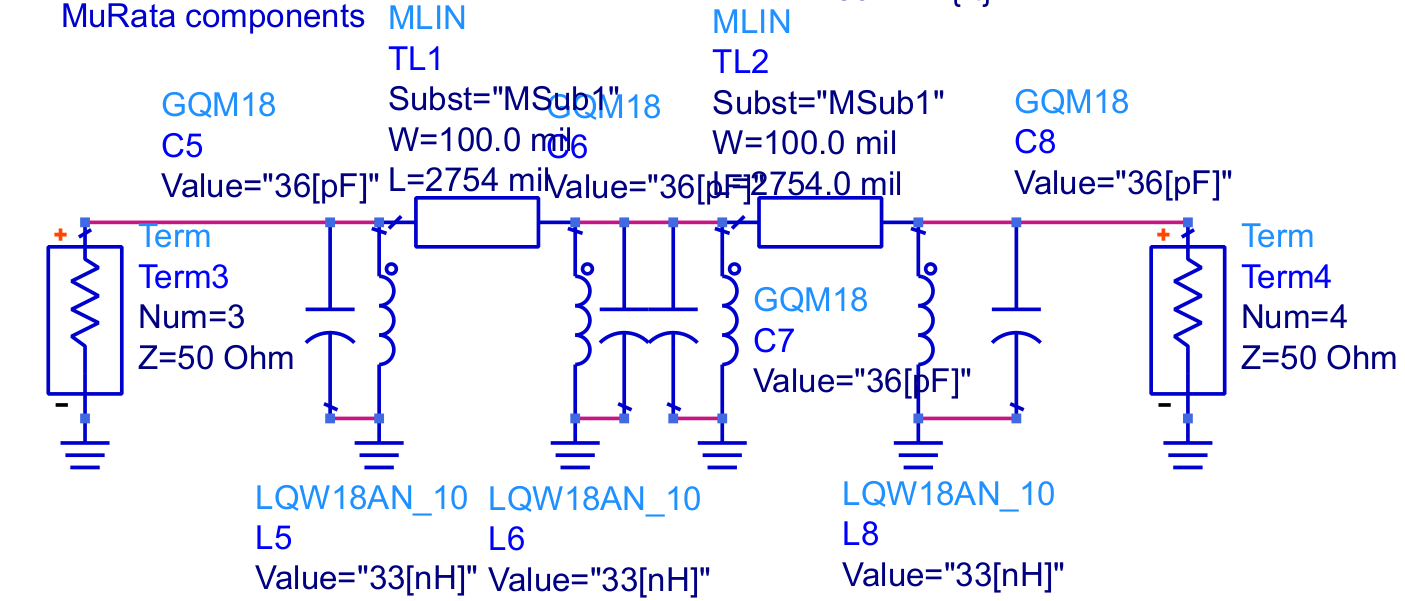
This is used to calculate the lumped elements on either side of a transmission line with a given electrical length to replace a diagonally-shorted pair of coupled lines with given even and odd characteristics at a given center frequency. In this specific case, a 144MHz bandpass filter with 0.5dB ripple (as discussed previously) comprised of two pairs of π/2 coupled lines is replaced by a pair of π/8 transmission lines with lumped elements. The closest actual values for the capacitors and inductors are 36pF and 33nH, respectively. For the models, I chose parts from the MuRata GQM and LQW series, using their design kit. Figure 5 shows the schematic of the resulting transmission line filter. Linecalc is used to calculate the physical characteristics of the transmission line segments.
Figure 5: Two-stage transmission line and lumped element filter with MuRata parts
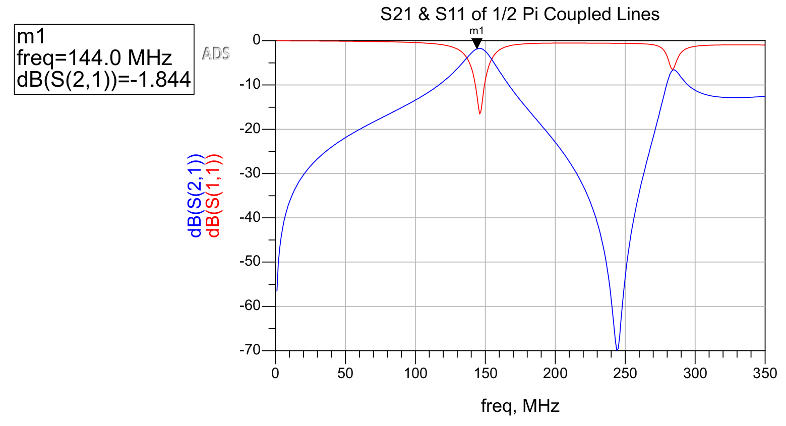
This circuit is then simulated in ADS. The behavior of the original coupled line filter is shown in Figure 6, and that of the reduced-size transmission line and lumped element filter is shown in Figure 7.
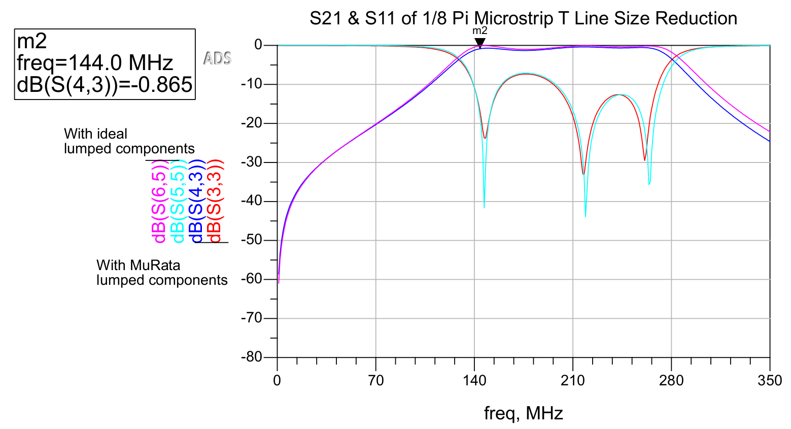
Figure 6: Insertion loss and return loss of a two-stage 144MHz coupled line bandpass filterFigure 7: Insertion loss and return loss of transmission line and lumped element equivalent filter, with ideal and MuRata lumped components
As is evident in Figure 7, the effects of using non-ideal lumped components are minimal, as opposed to the effects of non-ideal components in filters that make use of only lumped components. Transmission line filters with lumped components can be advantageous in attaining both a favorable match (due to resonance) as well as a low insertion loss in the passband.
Interestingly, the resulting passband is far wider in the transmission line filter. This could likely be remedied by adding more elements and through further tuning, or by investigating the cascaded impact of the fractional bandwidth used to derive the even and odd characteristics of the original coupled line filter. It is also possible that resonant characteristics of the transmission lines produces this effect.
As far as size reduction, each of the two coupled line pairs in the original filter is approximately 11.3 inches in length, while the transmission line segments in the new filter are only about 2.8 inches, and could be reduced further. Although the length of the transmission lines in the resulting filter can theoretically be arbitrarily defined, performance is impacted when this value becomes excessively small.
This approach for designing VHF bandpass filters is convenient in allowing the low-insertion loss of transmission line filters to be achieved in the small footprint of lumped-element filters, while also obtaining the favorable return loss and tight passband that resonant LC circuits can provide.
[2] M, Abhinaya, B, B., Dashora, H., & Kumar, J. (2020). Design and implementation of coupled line bandpass filter at c-band. AIJR Preprints. https://doi.org/10.21467/preprints.232
In Solar APRS Weather Station Published: 23 Jul 2023; Last edited: 23 Jul 2023 See just this article
My arduino-controlled AD9850-based APRS transmitter is one application that requires small and low-loss VHF filters. More specifically, a sharp-cutoff bandpass filter is required to reduce mixing products and harmonics thereof below the legal limit. The initial approach was to use a 5th order LC Chebyshev bandpass filter.
Prior to using Keysight's Pathwave ADS, this filter was simulated in LTSpice with ideal components. Ideal components result in the filter working perfectly, but success with this design was practically far more challenging as a result of the nonexistence of ideal components. As documented in a previous post, the sharp-cutoff LC bandpass filter performed too poorly in the real world than could be useful, with a measured insertion loss of nearly 20dB in the passband.
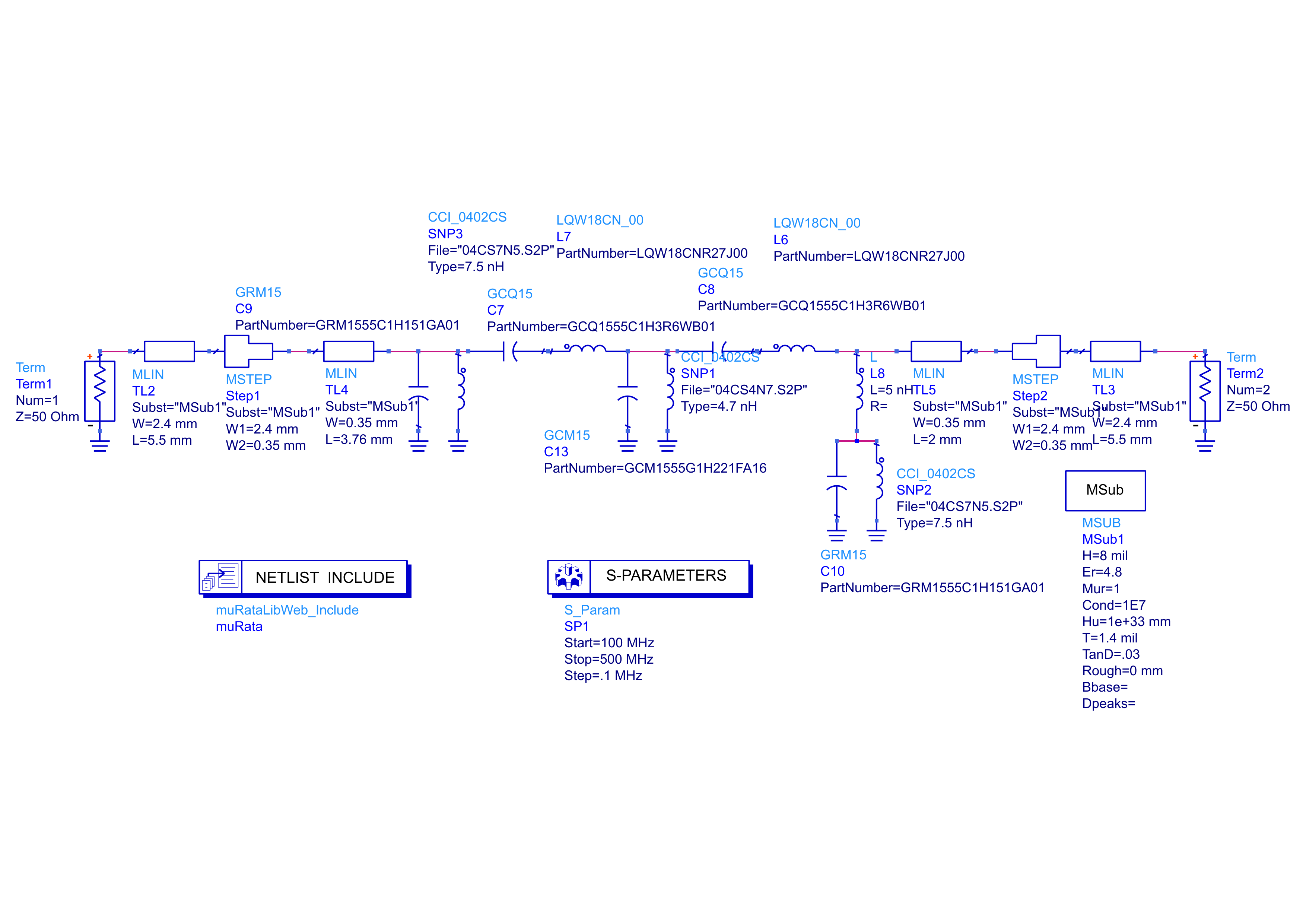
The first step after measuring unexpectedly attenuated waveforms about this filter was to build the filter on an pull-out structure that I included on the transmitter board for further testing with an SMA connector at each of its two ports. Upon measuring this with a NanoVNA pocket vector network analyzer, the 20dB insertion loss was observed. To confirm the plausibility of these results (being wary of measurement or calibration error), I created an identical schematic to the pull-out structure with this filter in a new ADS schematic, using models from MuRata's design kit for the MuRata components used. I tried to approximately model the microstrip transmission line to the SMA connectors using MLIN and MSTEP components in ADS after creating an MSub block with the parameters of the PCBWay board. The schematic is shown in Figure 1:
Figure 1: Schematic and simulation setup for the original lumped-element bandpass filter
The NanoVNA was connected with the NanoVNASaver software to save a touchstone file for comparison with ADS's S-Parameter simulation. Results are displayed in Figure 2:
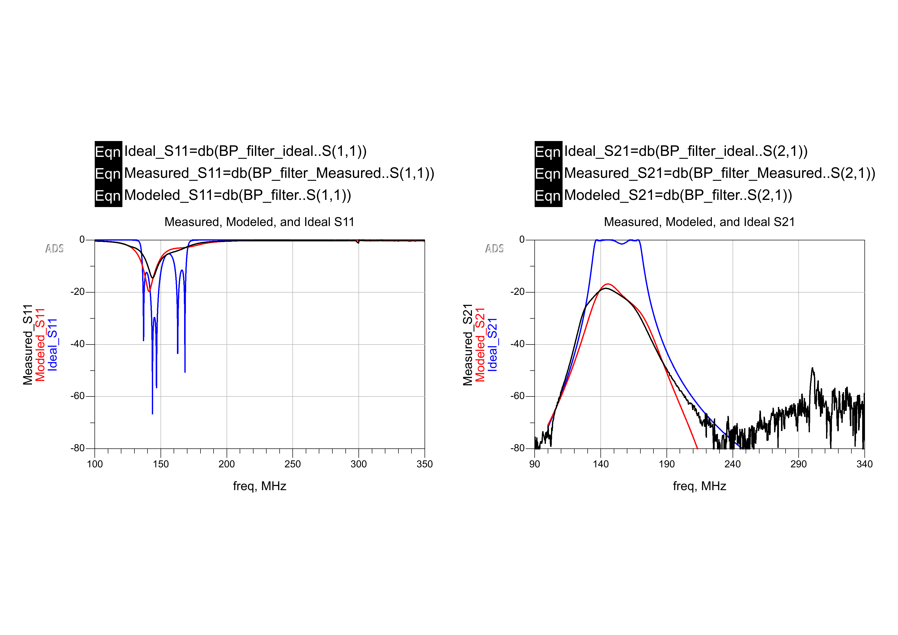
Figure 2: Measured vs. modeled with ideal and actual component models
The blue traces show what was initially expected, having initially simulated everything with ideal components. The red and black traces show what was modeled with actual component libraries in ADS and measured via the NanoVNA. Evidently, this bandpass filter is not usable for this application, as 20dB insertion loss in the passband removes far too much of the desired signal. While the return loss is very favorable in the 144MHz passband, the insertion loss in the passband is too significant. A different bandpass filter technology must be employed to combat this issue.
Parallel Coupled Lines as Chebyshev Bandpass Filters
Parallel quarter-wavelength coupled lines can be used to realize fairly low-loss bandpass filters with microstrip technology in some cases where LC filters might not be practical [1].
The elements of the bandpass filter can be treated as admittance inverters in order to derive coupled lines that take the place of the lumped elements [1].
Even and odd characteristics for parallel quarterwave coupled lines used to replace lumped elements in a symmetric chebyshev bandpass filter can be found by determining the characteristic admittances about each element [1, 3]. Even and odd characteristics for elements of a 0.5dB ripple chebyshev bandpass filter with a fractional bandwidth (3dB cutoff angular frequency delta over the center) of approximately 0.12 as calculated by Abhinaya et al. are listed in Table 1 [1].
Table 1: Even and odd characteristics of Chebyshev bandpass filter elements with 0.5dB ripple and Δ≈0.12 [1]
Element (1 through n)
Z0e (Ohms)
Z0o (Ohms)
1, n
72.025
38.929
2, n-1
57.282
44.382
3, n-2
55.844
45.274
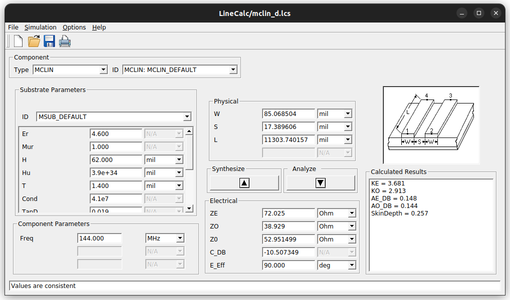
LineCalc is used to determine the physical parameters of microstrip coupled lines for a two-element bandpass filter about 144 MHz (see Figure 3). Both sets of coupled lines in this filter are identical, being the first and last (1, n in Table 1) elements in a symmetric filter. The substrate parameters used for the design of this filter are those from JLCPCB's capabilities from here on.
Figure 3: Linecalc to calculate physical parameters of coupled line microstrip
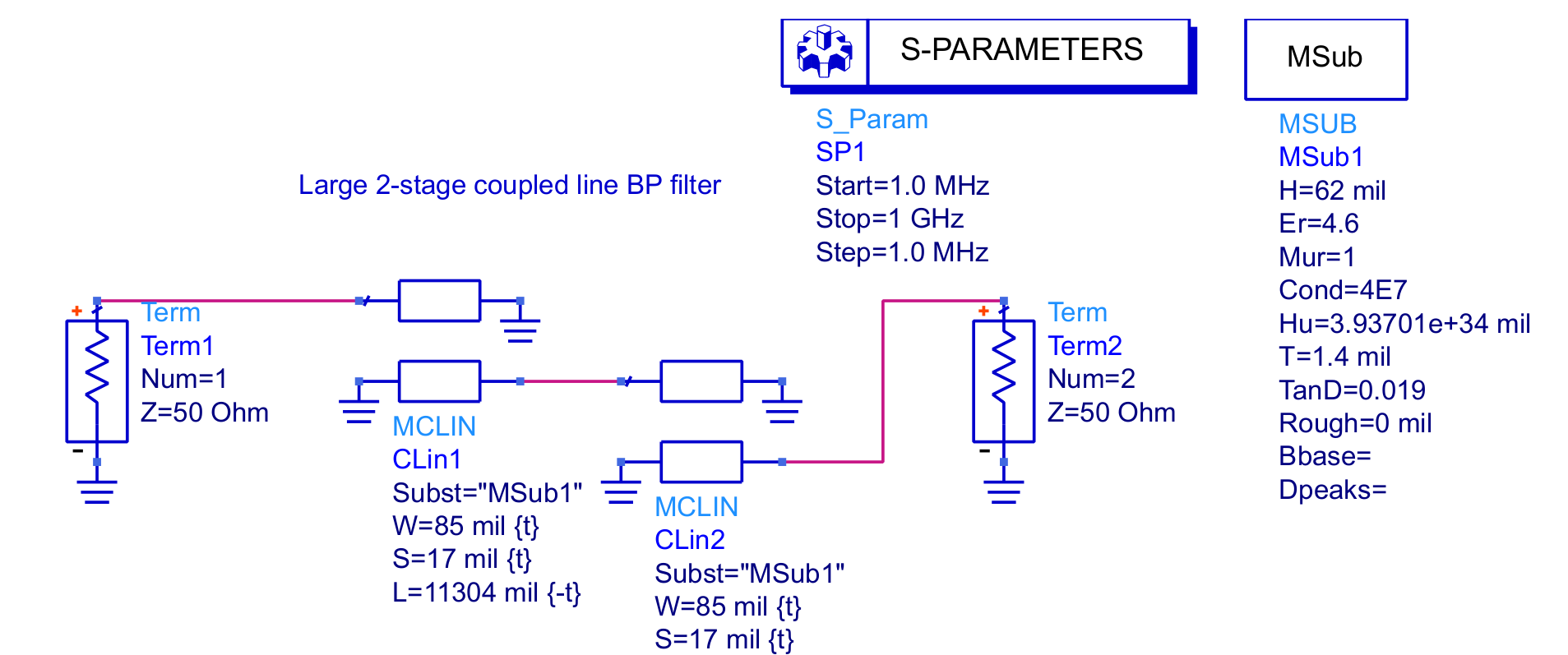
This is implemented in an ADS schematic (figure 4) as a pair of diagonally shorted coupled line pairs.
S parameter data from the simulation is shown in Figure 5.
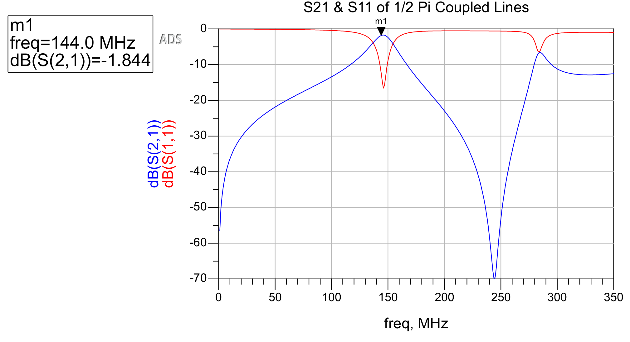
Figure 4: Schematic of the quarter-wave 144MHz coupled line bandpass filterFigure 5: Insertion loss and return loss of the simulated coupled line filter
As displayed in Figure 5, simulated insertion loss is far more acceptable than that of the original, lumped-element filter (shown in Figure 2). The rolloff is not nearly as steep, so for use in my transmitter design, more elements are required (more elements exist in the original, lumped-element filter). However, rejection of many of the mixing tones' harmonics around 250MHz is quite acceptable.
Each of these pairs of coupled lines is approximately 11.3 inches long. Because of this massive size at VHF frequencies, more elements might not be practical in most applications, including in my Arduino controlled APRS transmitter. Regardless, microstrip coupled line filters offer advantages over lumped-element equivalents in terms of loss and, depending upon size and constraints of PCB fabrication, potentially cost.
Simulation with non-ideal components and materials is extremely helpful in design of such devices because ideal components and materials cannot exist and often exhibit drastically different behavior in narrowband filters.
References
[1] M, Abhinaya, B, B., Dashora, H., & Kumar, J. (2020). Design and implementation of coupled line bandpass filter at c-band. AIJR Preprints. https://doi.org/10.21467/preprints.232
After almost 10 months, I am finally nearing the first production release of CubeServer, the software powering a school-wide engineering competition behind-the-scenes!
In Programming Tidbits Published: 29 Jun 2022; Last edited: 15 Jul 2022 See just this article
PyMongo bson EnumCodec
I found that Python Enum types could not be encoded into bson by default, so I created this abstract TypeCodec class for this purpose:
Note that this assumes the ENUM values are strings!
"""For encoding/decoding Enums into bson

Limitations:
Only works with Enums that have bson-compatible typed values
Enum values must all be of the same type
"""

from enum import Enum
from typing import Type
from bson import _BUILT_IN_TYPES as BSON_TYPES
from bson.codec_options import TypeCodec

__all__ = ['EnumCodec']

class EnumCodec(TypeCodec):
    """Codec for encoding a generic Enum into bson
    *This assumes the Enum only contains primitive/built-in/bson-compatible
    types*"""

    def __init__(self, enum_class: Type[Enum], value_class: type):
        """Specify the enum class to encode/decode
        and the type of the Enum's values.
        The value class MUST be DIRECTLY bson-compatible!"""
        assert value_class in BSON_TYPES, \
            "Enum values must be DIRECTLY bson-compatible."
        assert all(isinstance(val.value, value_class) for val in enum_class), \
            "Enum values must all have the same type, as specified."

        self.enum_class = enum_class
        self.value_class = value_class

    @property
    def python_type(self):
        return self.enum_class

    @property
    def bson_type(self):
        return self.value_class

    def transform_python(self, value: Enum):
        return value.value

    def transform_bson(self, value) -> Enum:
        return self.python_type(value)
In Solar APRS Weather Station Published: 18 Apr 2022; Last edited: 18 Apr 2022 See just this article
Designing a Replacement Post-mixer Filter
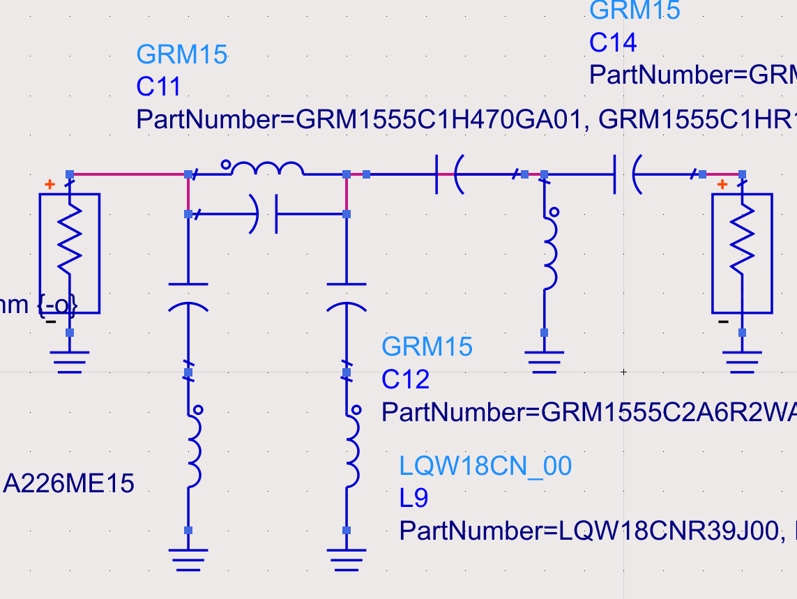
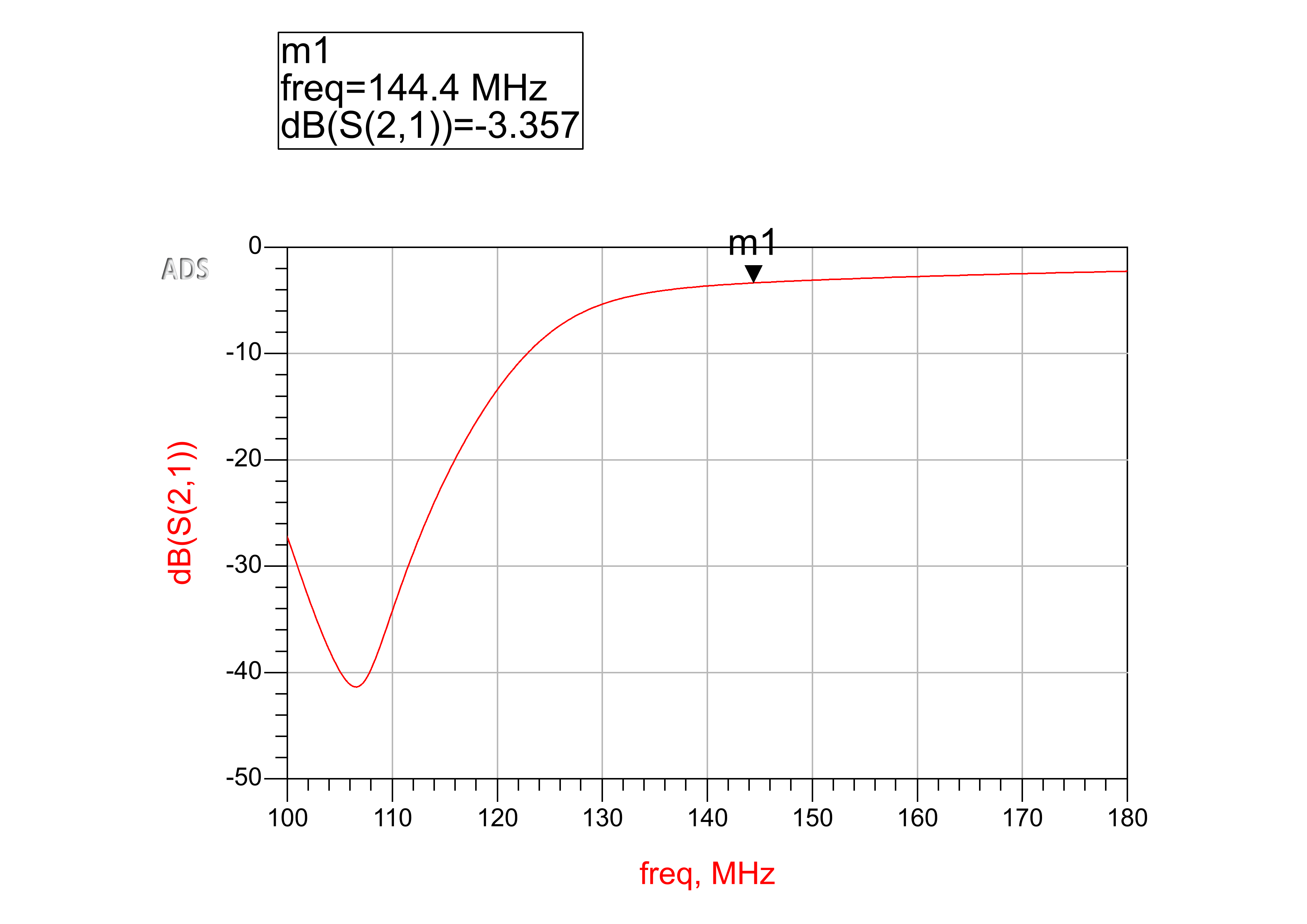
The current step is designing a filter which will limit the levels of unwanted tones, but only to an extent that allows for a reasonably strong signal in the passband so that the CMX901 PA receives a reasonably optimal input power, and touch up the signal after it has been amplified. I have been experimenting with different implementations of such a filter in Keysight's ADS; I am currently looking at using a notch filter to reduce the ~105 MHz signal from the mixer (which is equally strong as the desired 144.39 MHz signal) and a high-pass filter to limit any other tones that might be present:
This has what appears to be an acceptable response, as simulated with MuRata components:
However, the next step will be to measure another FFT from the actual board at the output of the RF mixer, which is data I have observed but not captured since modifying the LO signal amplification. With this data, it will be easier to design the most appropriate filter.
In Solar APRS Weather Station Published: 09 Apr 2022; Last edited: 18 Apr 2022 See just this article
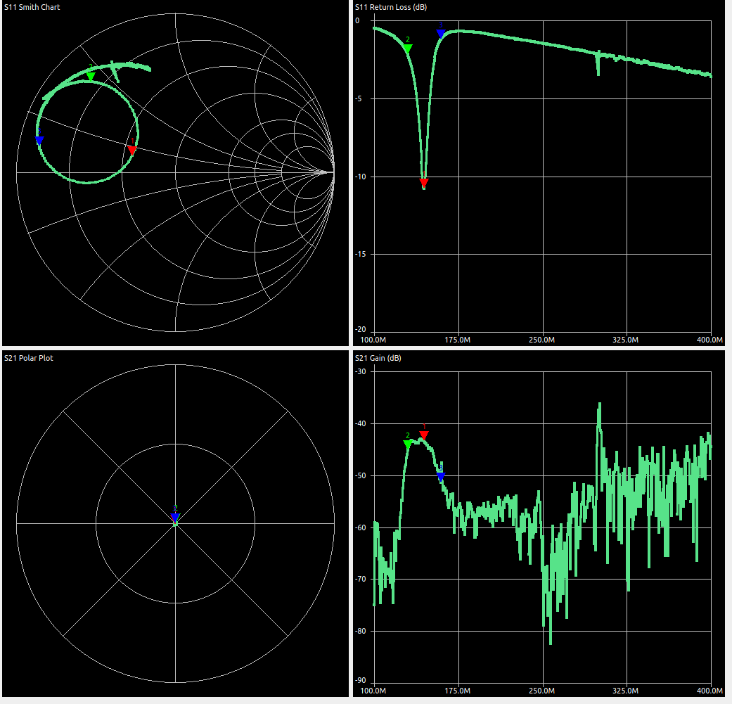
Measured Vs. Modeled of Existing Bandpass Filter
Using Keysight's Advanced Design System EDA, I created a basic model of the bandpass filter as it currently stands on the pull-out-structure:
This compares very closely to the measured values from the NanoVNA but is distinctly different from those from a simulation of ideal components:
I am currently considering two options:
Institute a high-pass filter instead of the bandpass filter and cut off harmonics after the PA with a phyisically bigger filter
Utilize a band-stop filter to reduce the cutoff that the bandpass filter must have to eliminate the 105.6 MHz unwanted mixer product.
In Solar APRS Weather Station Published: 25 Mar 2022; Last edited: 09 Apr 2022 See just this article
Post-Mixer BP Filter
With a reasonable signal at the output of the mixer, the next step is ensuring that only the 144.39MHz tone must be selected and amplified.
The initial measurements of the bandpass filter are as follows, with a rediculus amount of loss in the passband:
Upon simulating in LTSpice (I had generated the filter with Marki Microweave's online filter calculator, and trusted the S-Parameters it generated), it became clear that this filter only works with perfect components. As soon as the slightest amount of ESR is added, it performs terribly.
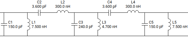
I tried tweaking the parameters in the calculator and wound up with the following filter:
The 300nH inductors are replaced with 270nH ones because LTSpice indicated it would still work. I will update with more info surrounding this topic.
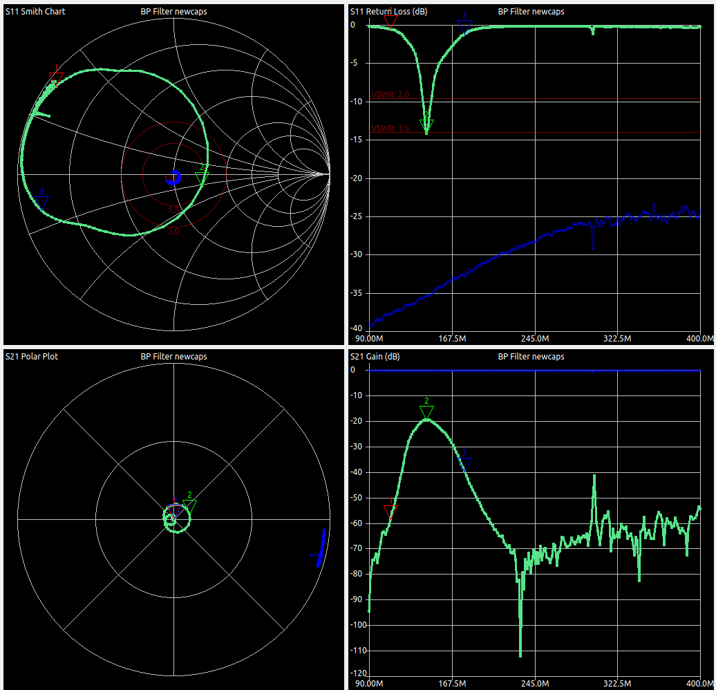
The new filter displays better, but still unusable performance, as measured by the NanoVNA:
In Solar APRS Weather Station Published: 01 Mar 2022; Last edited: 05 Jun 2022 See just this article
LO Signal Path Debugging
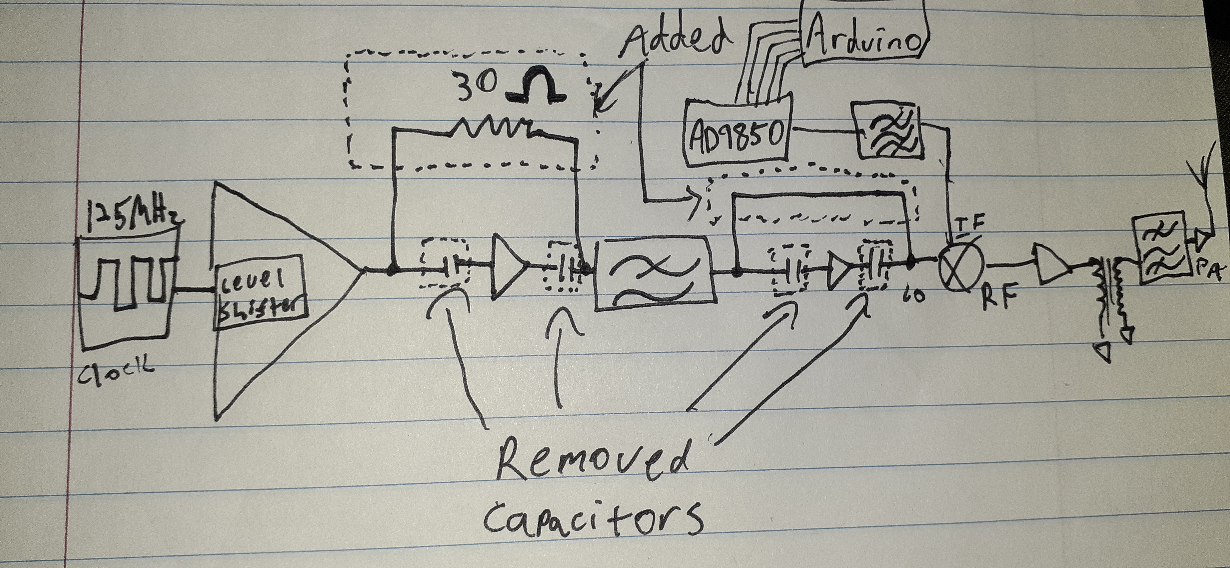
Due to a few components having the wrong exponent (being 0.1nH instead of 0.1uH-- big difference!), the common-emitter amplifiers to boost the LO signal from the LVDS receiver have very little gain. To mitigate this issue, the 2N2222 transistors were swapped out for MMBTH10s, which can have quite a bit of gain at VHF frequencies. Using the board's solder-jumper-based configurability, the 3v to 5v level shifter was inserted to boost/buffer the signal before the MMBTH10 amplifier, a low-pass filter, and another amplifier. However, the signal from the level shifter was found to be sufficient on its own. The transistor amplifiers need some additional thought if they are to remain in the design.
I soldered a 30Ω axial resistor onto the 0402 pads to bypass the first amplifier stage from the level shifter output to the input of the LP filter. I then disconnected the appropriate DC-block capacitors to isolate the amplifiers, and connected the output of the filter to the LO input of the mixer, as outlined in the following diagram:
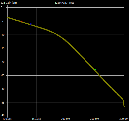
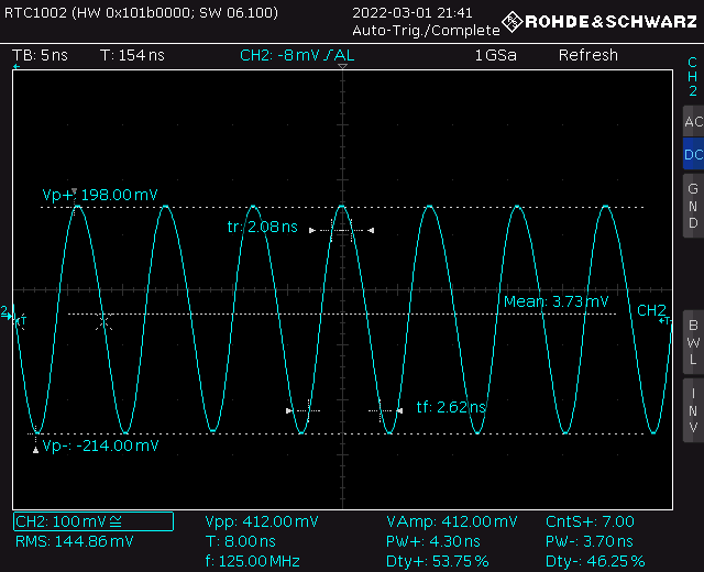
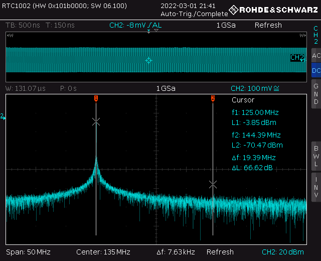
The filter, as measured with a NanoVNA with NanoVNASaver, has roughly 5db of loss at 125MHz (the red marker), and roughly 23db at the second harmonic (green marker), only about a db different from simulated:
The LO signal at the input of the mixer is now more reasonable:
In Solar APRS Weather Station Published: 05 Feb 2022; Last edited: 18 Apr 2022 See just this article
The Case of the Missing LO Signal
Note (update): These initial measurements were measured with poor-quality probes, which was the cause of their peculiarity (spoiler alert). See the update at the bottom for more information.
Before installing the transformer T1, the impedance that the amplifier at the RF output of the mixer was high enough that and RF signal was seen at the output of the mixer:
However, the LO signal is too low to produce a measurable signal at the RF output of the mixer now that the transformer has been installed.
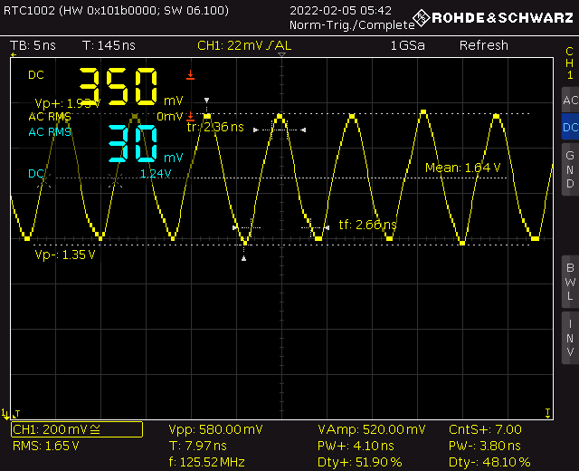
This is because the DS90LV028ATM is only providing about 580mV peak-to-peak, as opposed to the ~1-1.5 volts I had expected.
Luckily, the board has provisions such that this signal can be boosted by a level shifter:
Changing JP5, JP8, JP9 should allow the LVDS receiver's output to be boosted to a 5v logic signal. However, the LVDS receiver's outputs are not compatible with 3v logic in this situation in terms of voltage, being centered around 1.64, which should appear as a high. It is likely that one of the outputs is being dragged down such that neither works properly.
UPDATE: As it turns out, the cause of this symptyom was poor measurement. When I switched to 300MHz Rohde & Schwarz probes (as opposed to unknown probes), the signals behaved as expected.
To use the AD9850 module as a signal generator and to provide convenient control over the IF while testing the circuit, I wrote a quick test program for arduino (partially based off of examples):
#include <Arduino.h>
#include <AD9850SPI.h>
#include <SPI.h>
#include <string.h>

const int W_CLK_PIN = 13;
const int FQ_UD_PIN = 4;
const int RESET_PIN = 5;

double freq = 1000000;
double trimFreq = 124999500;

int phase = 0;

const byte maxChars = 32;
char receivedChars[maxChars];   // an array to store the received data

void printParams(void);
bool recCommand(void);

void setup(){
  Serial.begin(9600);
  DDS.begin(W_CLK_PIN, FQ_UD_PIN, RESET_PIN);
  DDS.calibrate(trimFreq);
  DDS.setfreq(freq, phase);
  Serial.println("+-------------------------+");
  Serial.println("|   AD9850 Test Program   |");
  Serial.println("| Joseph R. Freeston 2022 |");
  Serial.println("+-------------------------+");
  Serial.println();
  printParams();
  Serial.println();
  Serial.println();
  Serial.println("Enter a command.");
  Serial.println("Begin with either R, F, U, P, or D and an optional float following the first character.");
  Serial.print(">>> ");

}

void loop(){
  if(recCommand()) {
    if(receivedChars[0] == 'F') {         // Set frequency
      freq = atof(&receivedChars[1]);
      DDS.setfreq(freq, phase);
    } else if(receivedChars[0] == 'R') {  // Set reference
      trimFreq = atof(&receivedChars[1]);
      DDS.calibrate(trimFreq);
    } else if(receivedChars[0] == 'P') {  // Set phase
      phase = atof(&receivedChars[1]);
      DDS.setfreq(freq, phase);
    } else if(receivedChars[0] == 'U') {  // Up
      DDS.up();
    } else if(receivedChars[0] == 'D') {  // Down
      DDS.down();
    } else {
      Serial.println("Invalid command. Begin with either R, F, U, P, or D and an optional float following the first character.");
    }
    printParams();
    Serial.print("\n>>> ");
  }
}

void printParams() {
  Serial.println("------------------------------");
  Serial.print("Reference set to ");
  Serial.print(trimFreq, DEC);
  Serial.println("Hz");
  Serial.print("Frequency set to ");
  Serial.print(freq, DEC);
  Serial.println("Hz");
  Serial.print("Phase set to ");
  Serial.print(phase*11.25, DEC);
  Serial.println("°");
  Serial.println("------------------------------");
}

bool recCommand() {
  static byte i = 0;
  const char endMarker = '\n';
  char rc;

  while (Serial.available() > 0) {
    rc = Serial.read();
    Serial.write(rc);

    if(rc != endMarker) {
      receivedChars[i] = rc;
      if(i < maxChars) i++;
    } else {
      receivedChars[i] = '\0';
      i = 0;
      return true;
    }
  }
  return false;
}
Then, in the serial terminal, the arduino can be given the following commands:
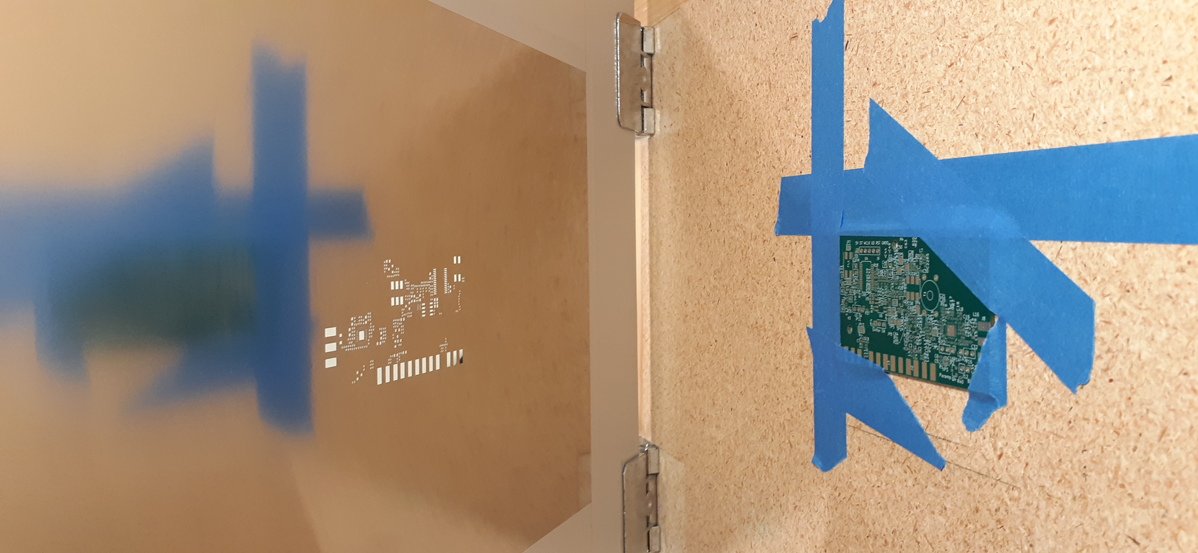
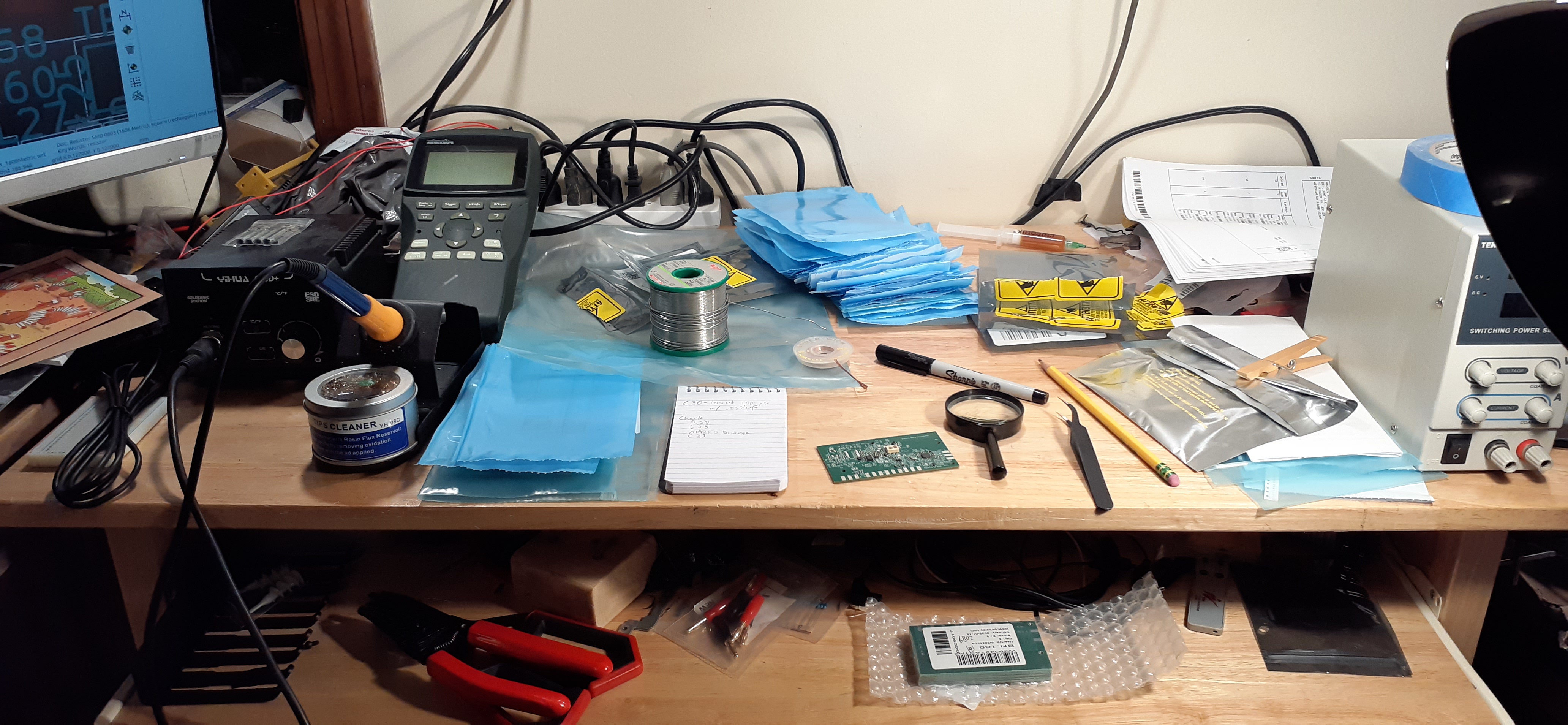
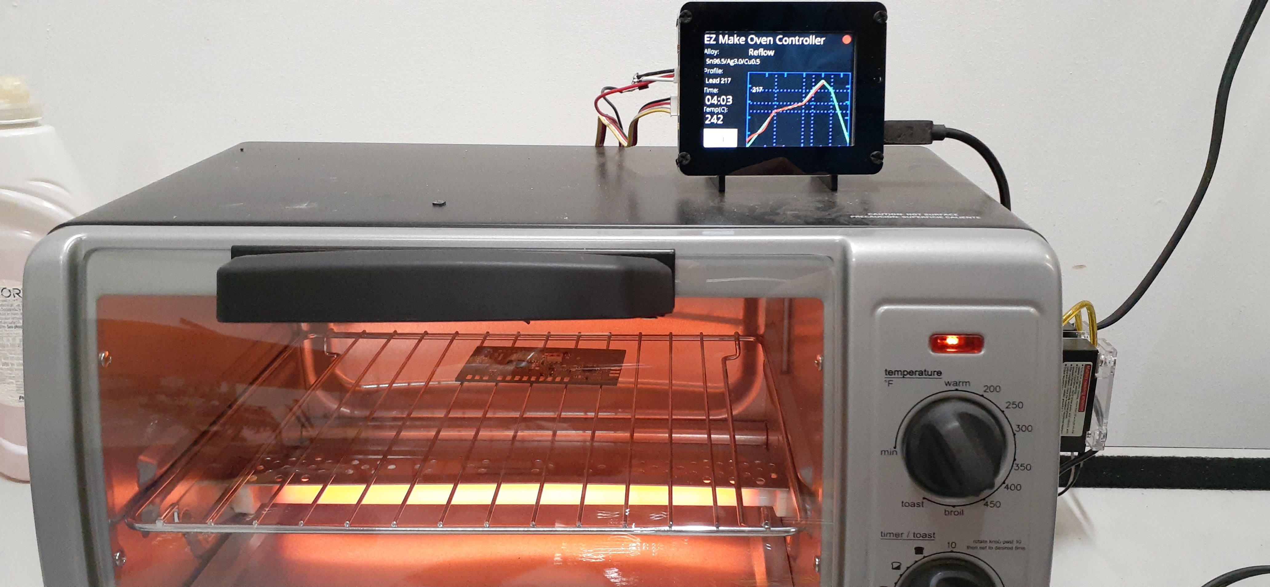
Screenprinting solder paste onto the boardPlacing the mostly 0402 componentsReflowing in EZ make reflow ovenBoard after hand-soldering the pin headers.
In Home Biology Lab Published: 11 Jan 2022; Last edited: 30 Jan 2022 See just this article
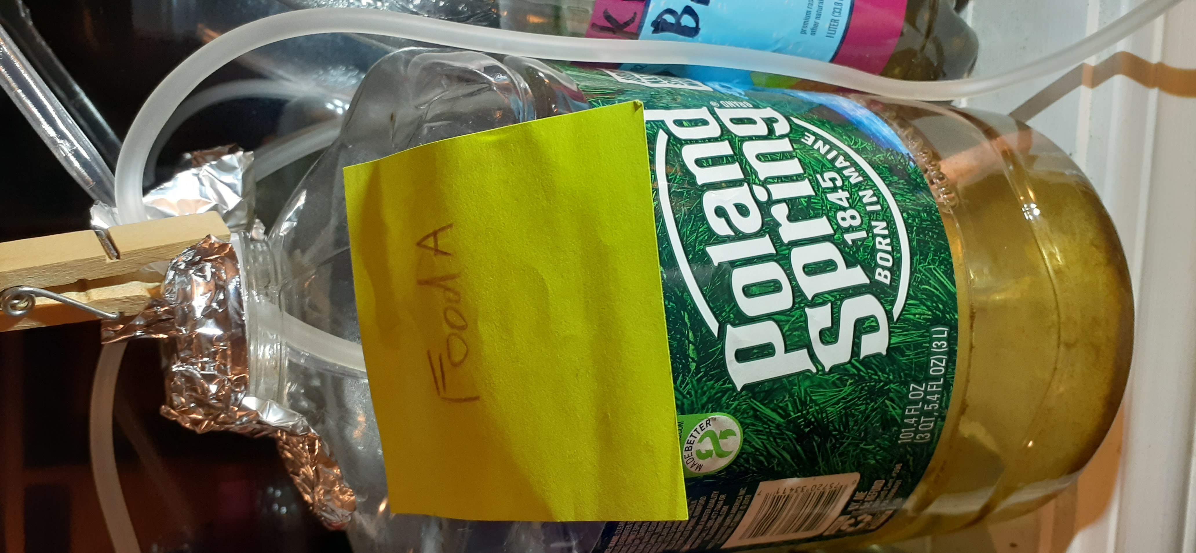
Culture Food-A
This post describes the status of the culture labeled "Food A".
Log:
Origin: water & detritus from the western region of a drainage stream, strained through a rag.
- Placed in window receiving sunlight
01/08/22- bubbler added
Large population of paramecia, bacteria, algae, and some diatoms
Culture Tardigrade B has been started as a combination of this and the original Hypsibius dujardini culture from Carolina.
Culture dish "snapshot" saved before adding bubbler-- Food A'
01/26/22- Culture Tardigrade C created between Tardigrade B and Food A in order to expand.
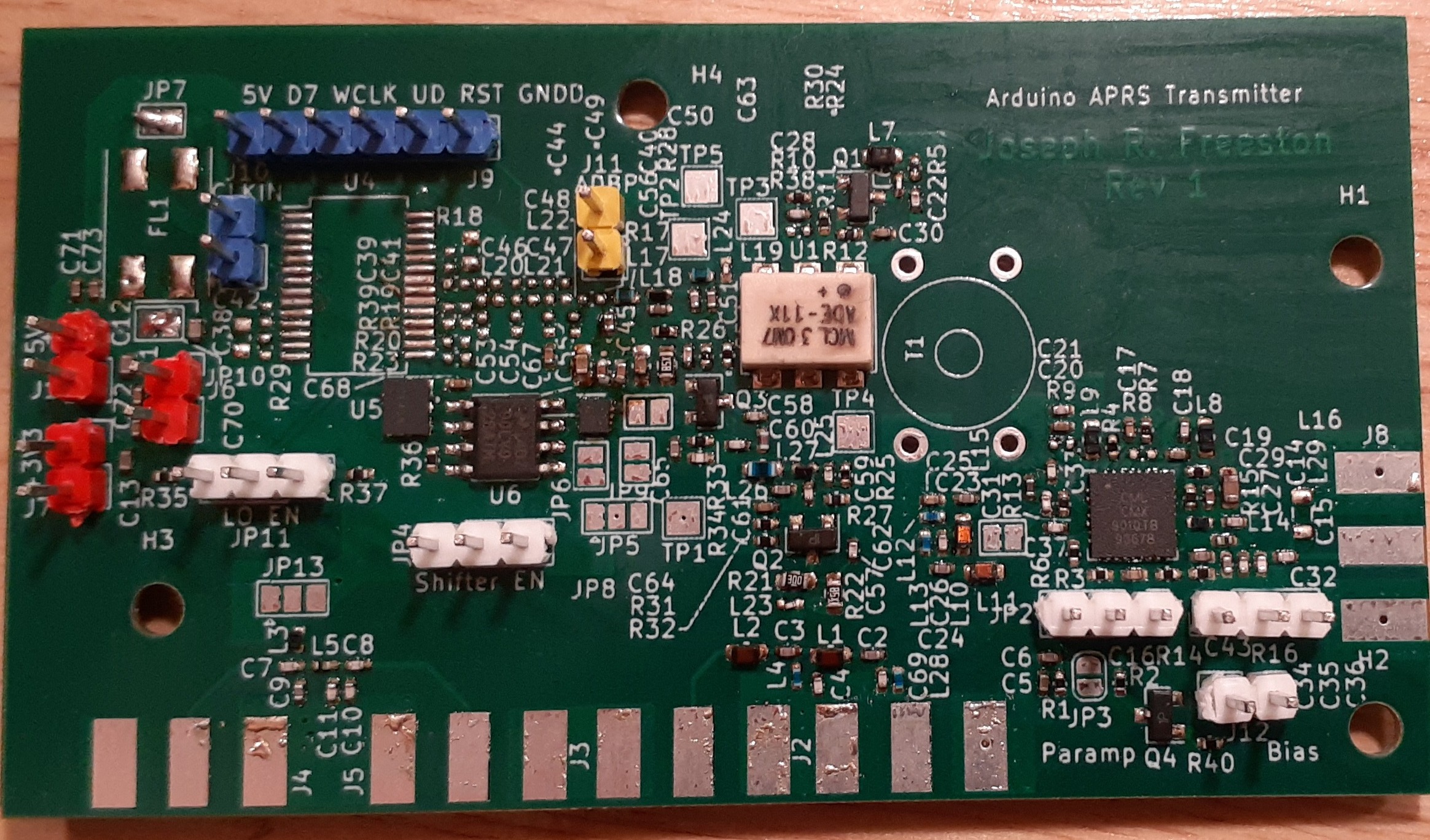
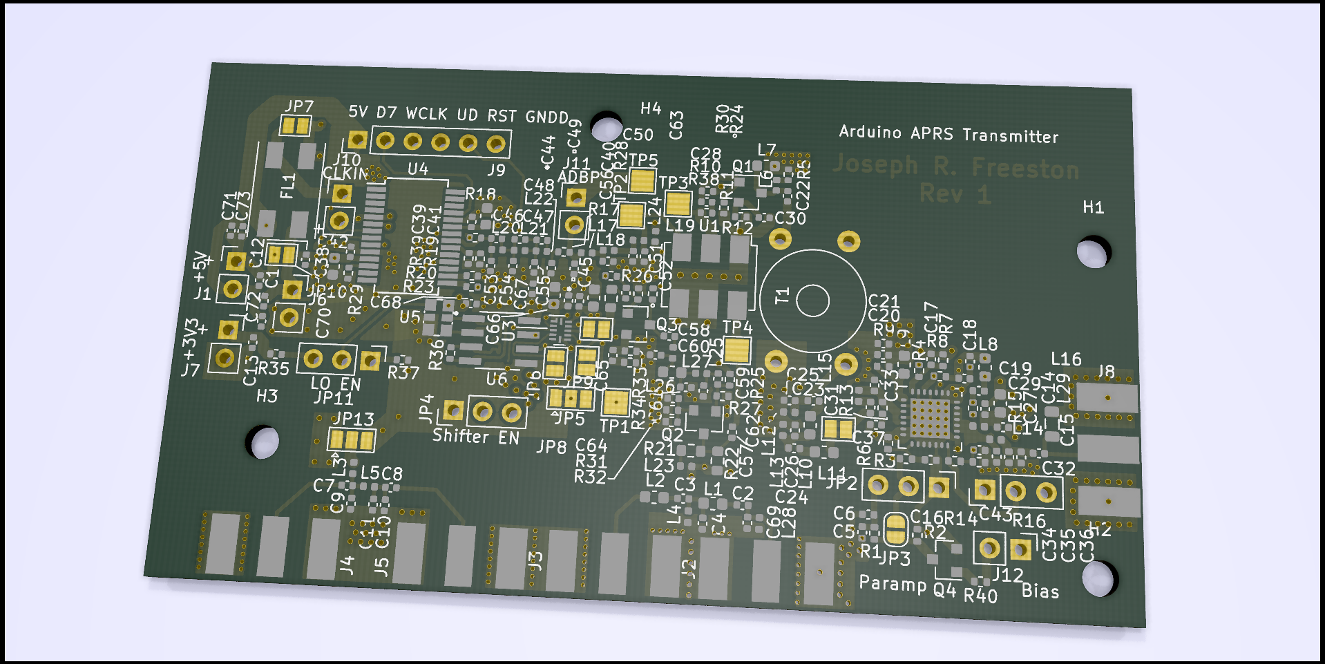
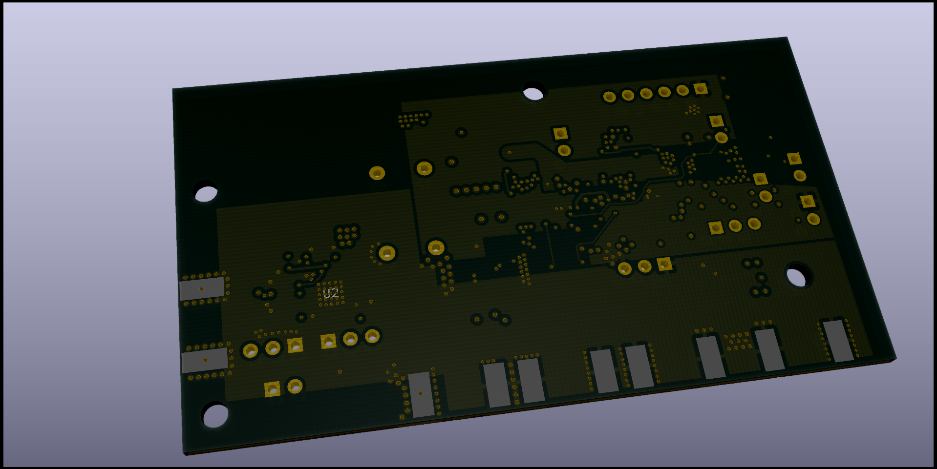
I have completed the first revision of the PCB design for the APRS radio.
3D renderings from KiCAD:
In Solar APRS Weather Station Published: 30 Nov 2021; Last edited: 30 Nov 2021 See just this article
APRS Transmitter Rev 1
The first revision of the Arduino APRS transmitter is designed.
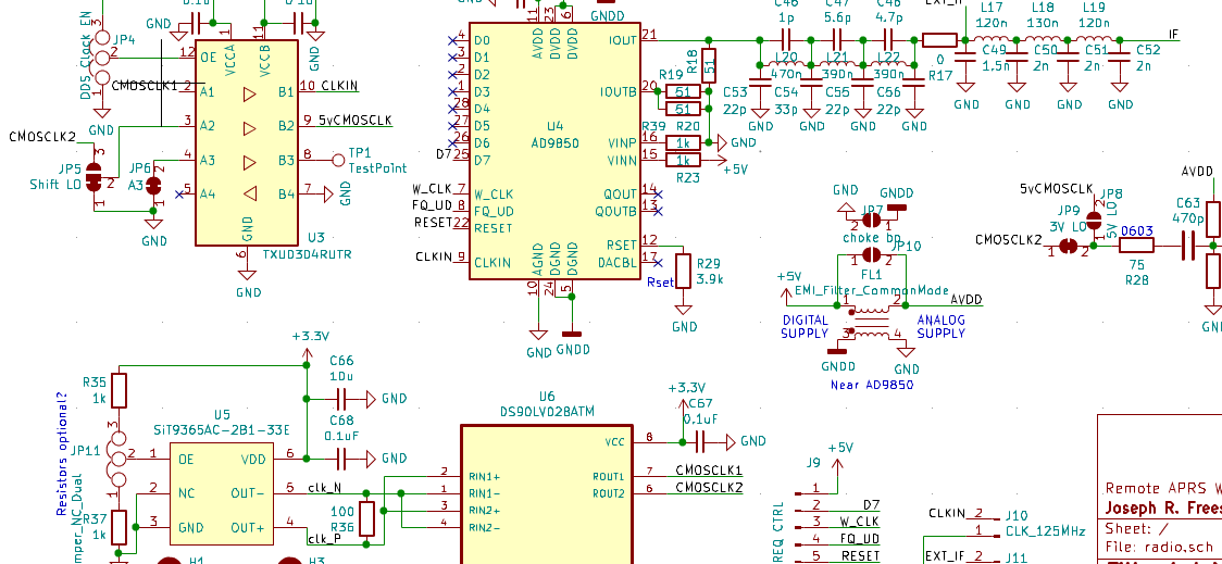
The LVDS signal from the SiT9365AC 125MHz clock source is terminated into both inputs of the DS90LV028ATM CMOS LVDS receiver. A level shifter makes this singal compatible as a clock signal for the AD9850 DDS synthesizer that will generate the IF frequency. The IF is then filtered to reduce the harmonic content of the synthesizer's output. The IF signal will be around 19.39 MHz. The other output of the LVDS receiver is buffered, filtered, and amplified by common-emitter amplifiers with 2N2222 transistors in order to form the LO signal. The two signals are multiplied by an ADE-11X+ VHF mixer, whose output is amplified and filtered to remove all but the desired frequency of 144.39 MHz. This signal is then amplified by a CMX901 power amplifier. Impedance matching was taken into consideration.
The current schematic (which is very likely to change) is shown below:
In Solar APRS Weather Station Published: 03 Oct 2021; Last edited: 12 Oct 2021 See just this article
Transmitter Local Oscillator
I initially had decided to use a DSC1001-series MEMS oscillator because they seem to be a common, fairly priced series of MEMS-based clocks. However, the absolute maximum ratings of having a minimum load resistance of 10kΩ, and a maximum capacitance of 15pF, was a significant design constraint. I searched for amplifiers, transistors, buffers, drivers, etc. to turn the high impedance signal into one that could be filtered, however these constraints were such that it was difficult to tell if any of the components that I had selected would actually function well with it. With some additional research, I stumbled upon the SiT9365 differential oscillator, which is better-suited to this application to begin with. Having a 30mA output current is much more flexible and conducive to a practical usage of this part as the local oscillator, but the supply current draw is, at the same time, significantly greater, posing a greater challenge for the solar power system.
In Solar APRS Weather Station Published: 03 Oct 2021; Last edited: 07 Feb 2022 See just this article
Intended Simplified Theory of Operation of the Transmitter
The IF will be between ~1 and ~40 MHz, as per the limitations of the AD9850 board.
As the RF output frequency will be 144.390 MHz, it seems that the best LO frequency would be 125 MHz, with an IF frequency of around 19.390 MHz, adding to 144.390. This allows for what seems to be the most separation between fLO + fIF and fLO - fIF while using a common crystal oscillator frequency of 125.000 MHz.
The AFSK will be accomplished via software-based frequency modulation (FM) of the intermediate frequency (IF) with the AD9850 board. This signal will be multiplied with the local oscillator (LO), which will be a 125MHz crystal oscillator chip. In-between these components will reside filtering, matching, buffering/driving, and amplification circuits to allow things to work properly without spewing noise and harmonics across the band. The output power will also be QRP, as the only goal is to reach a digipeater from the transmitter. A directional yagi antenna might become useful for making the most use of the QRP signal (which will ultimately be generated by solar power!!) from a fixed station.
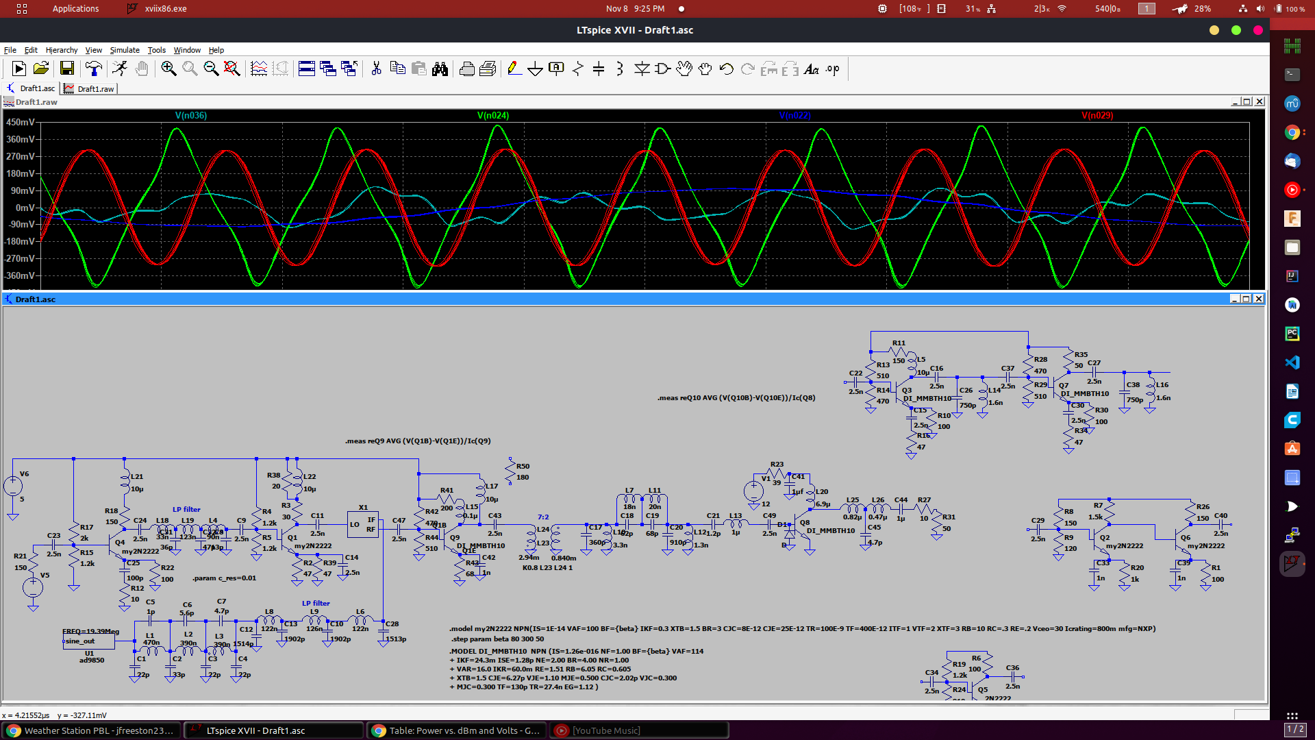
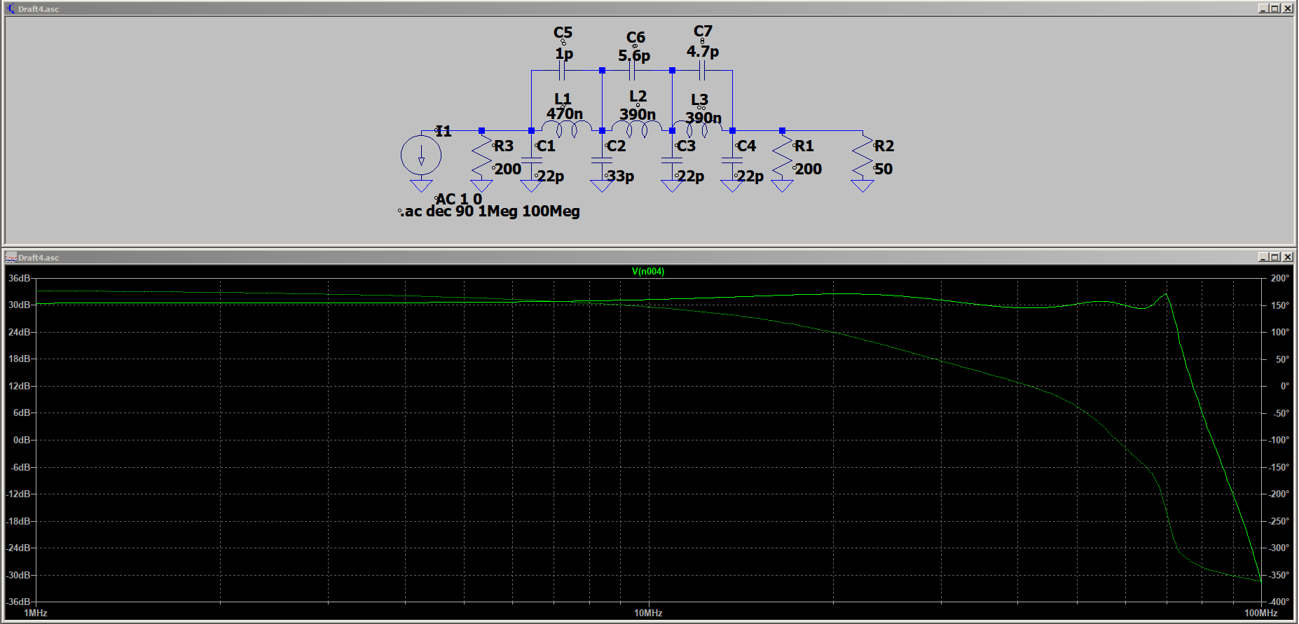
In order to simulate a radio transmitter using the AD9850 module, I created a model for the output of this module. The primary sine wave output is filtered by a low-pass filter which cuts off harmonics above 100Mhz:
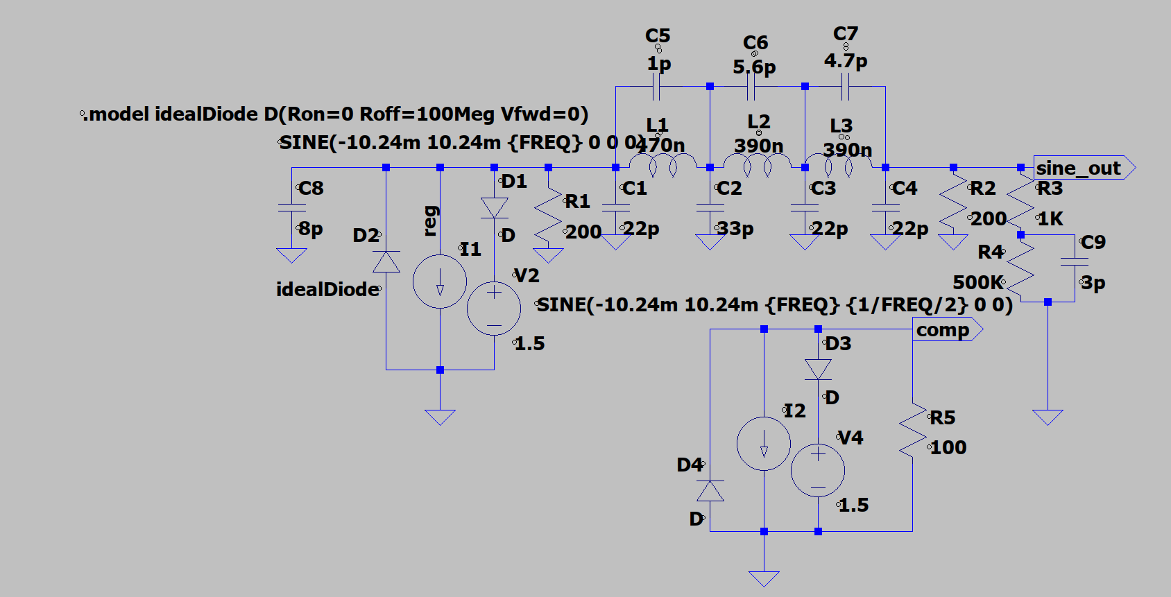
However, this filter is not present on the complimentary output of the module. Thus, I modeled the module's sine wave outputs with the following schematic:
The current source is modeled with voltage sources and ideal diodes in parallel to set a maximum and minimum voltage compliance output, a handy trick I learned from a Youtube video.
It will be interesting to see how closely this actually models the device.
I found that my reverse SSH tunnel with autossh was not persistent.
The remote server reboots daily, with the local machine (to which the server's requests are forwarded) rebooting weekly. The tunnel was exiting each time the remote server restarted, meaning that it was only persistent for one day each week. My script to establish tunnels is now as follows:
In Hosticlefifer (Website updates) Published: 27 Aug 2021; Last edited: 27 Aug 2021 See just this article
The Blog is Working!
The blog page is working!
I created this blog from scratch using PHP, Doctrine, Bootstrap, and Prism. This will hopefully serve as a useful and reasonably formal medium for documenting my projects.
It can display little pictures:
... medium-sized pictures:
... big images:
... bigger images:
... samples of code:
import time
import sys

print("Hello, %s !" % sys.argv[1])

while True:
    print("This is an example Python program!!")
    time.sleep(1)