Due to a few components having the wrong exponent (being 0.1nH instead of 0.1uH-- big difference!), the common-emitter amplifiers to boost the LO signal from the LVDS receiver have very little gain. To mitigate this issue, the 2N2222 transistors were swapped out for MMBTH10s, which can have quite a bit of gain at VHF frequencies. Using the board's solder-jumper-based configurability, the 3v to 5v level shifter was inserted to boost/buffer the signal before the MMBTH10 amplifier, a low-pass filter, and another amplifier. However, the signal from the level shifter was found to be sufficient on its own. The transistor amplifiers need some additional thought if they are to remain in the design.
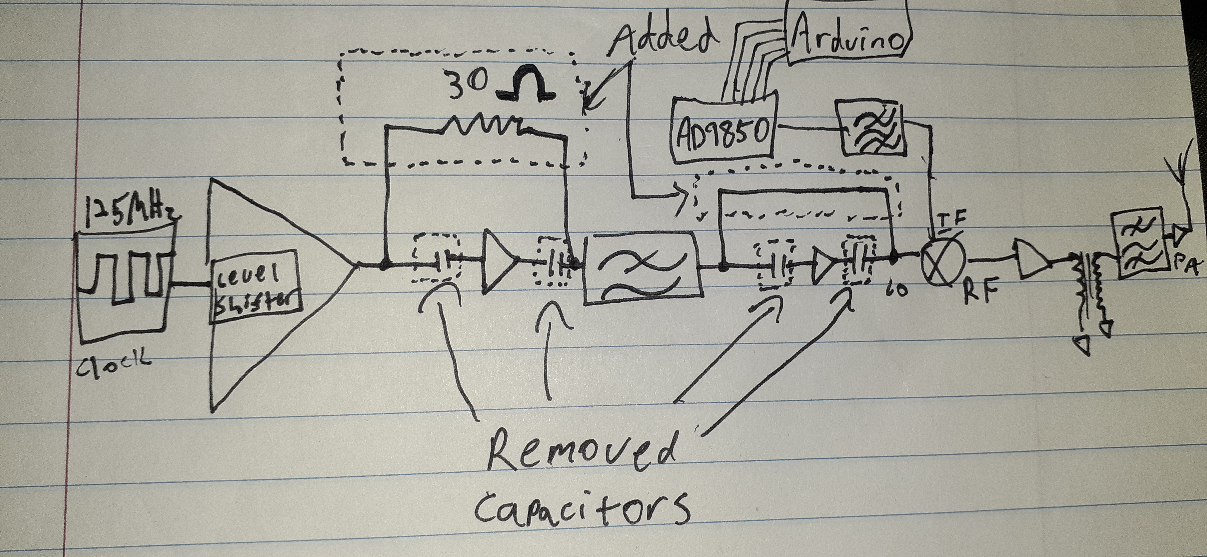
I soldered a 30Ω axial resistor onto the 0402 pads to bypass the first amplifier stage from the level shifter output to the input of the LP filter. I then disconnected the appropriate DC-block capacitors to isolate the amplifiers, and connected the output of the filter to the LO input of the mixer, as outlined in the following diagram:
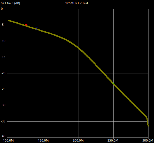
The filter, as measured with a NanoVNA with NanoVNASaver, has roughly 5db of loss at 125MHz (the red marker), and roughly 23db at the second harmonic (green marker), only about a db different from simulated:
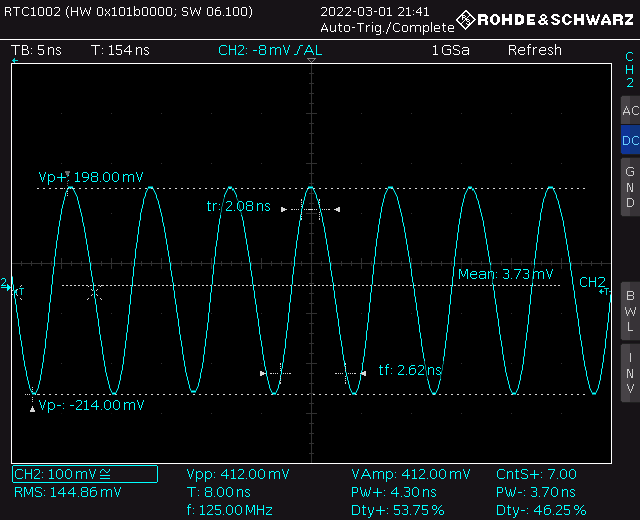
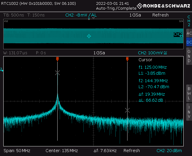
The LO signal at the input of the mixer is now more reasonable: