Introduction
As previously discussed, coupled microstrip filters can offer improved performance over filters comprised solely of lumped elements in some cases. Coupled-line microstrip filters are common at sufficiently high frequencies when the physical size can be very small. However, at VHF frequencies, traditional quarter-wavelength coupled lines can be too large for most applications. Additionally, having a smaller element size allows filters to have more elements (and a potentially much sharper cutoff) within the same size constraints.
Transmission Line and Lumped-Element Bandpass Filters
The behavior of a diagonally-shorted quarter-wavelength pair of coupled lines can be approximated with an arbitrary-length transmission line with lumped elements on either side [1]. This has the effect of better rejection outside of the passband, reducing transmission at some of the harmonics of the passband [1]. To determine the values of the lumped elements (a shunt capacitor and inductor on either side of the resulting transmission line), analysis of characteristic impedance can be used to relate the diagonally shorted coupled lines to the transmission line between lumped elements [1]. Kang and Xu simplified this relationship into the equations in Figure 1.
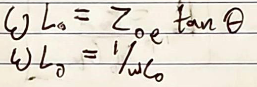
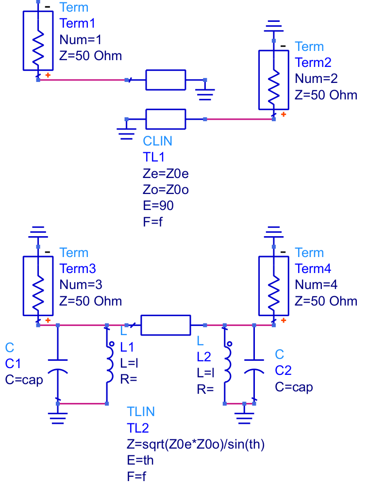
To confirm this relationship, variables in ADS were created based on these equations (Figure 2), and the simplified equivalent circuits were modeled with ideal components (Figure 3).
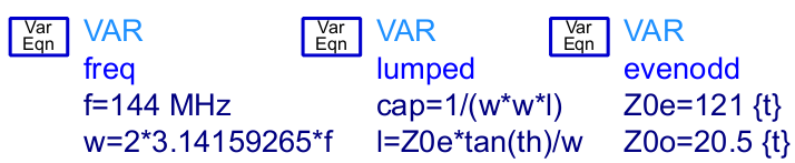
In Figure 2, above, "freq" defines the center frequency traditionally and in angular units, "cap" is the capacitance of the shunt capacitor on either end of the transmission line, "l" is the inductance of the shunt inductor on either side of the transmission line, "Z0e" and "Z0o" are the even and odd-characteristic impedances of the coupled lines, and "th" is the electrical length of the arbitrary-length transmission line, in radians.
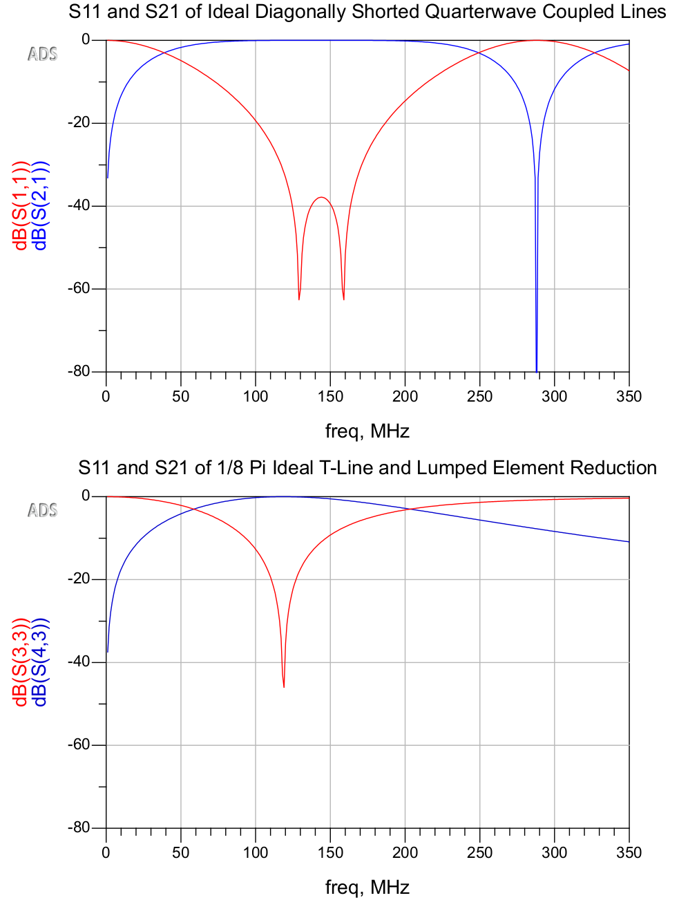
As is evident in Figure 4, the reduced transmission line circuit exhibits very similar characteristics as a bandpass filter. The primary discrepancies are that the harmonic passbands are attenuated, and, due to the resonant LCs, the return loss becomes unimodal and the passband becomes slightly narrower.
Such a filter could benefit from sharper rolloff from more elements, and should be simulated with non-ideal components. To facilitate the design process by the equations in Figure 1, I created the spreadsheet embedded below:
This is used to calculate the lumped elements on either side of a transmission line with a given electrical length to replace a diagonally-shorted pair of coupled lines with given even and odd characteristics at a given center frequency. In this specific case, a 144MHz bandpass filter with 0.5dB ripple (as discussed previously) comprised of two pairs of π/2 coupled lines is replaced by a pair of π/8 transmission lines with lumped elements. The closest actual values for the capacitors and inductors are 36pF and 33nH, respectively. For the models, I chose parts from the MuRata GQM and LQW series, using their design kit. Figure 5 shows the schematic of the resulting transmission line filter. Linecalc is used to calculate the physical characteristics of the transmission line segments.
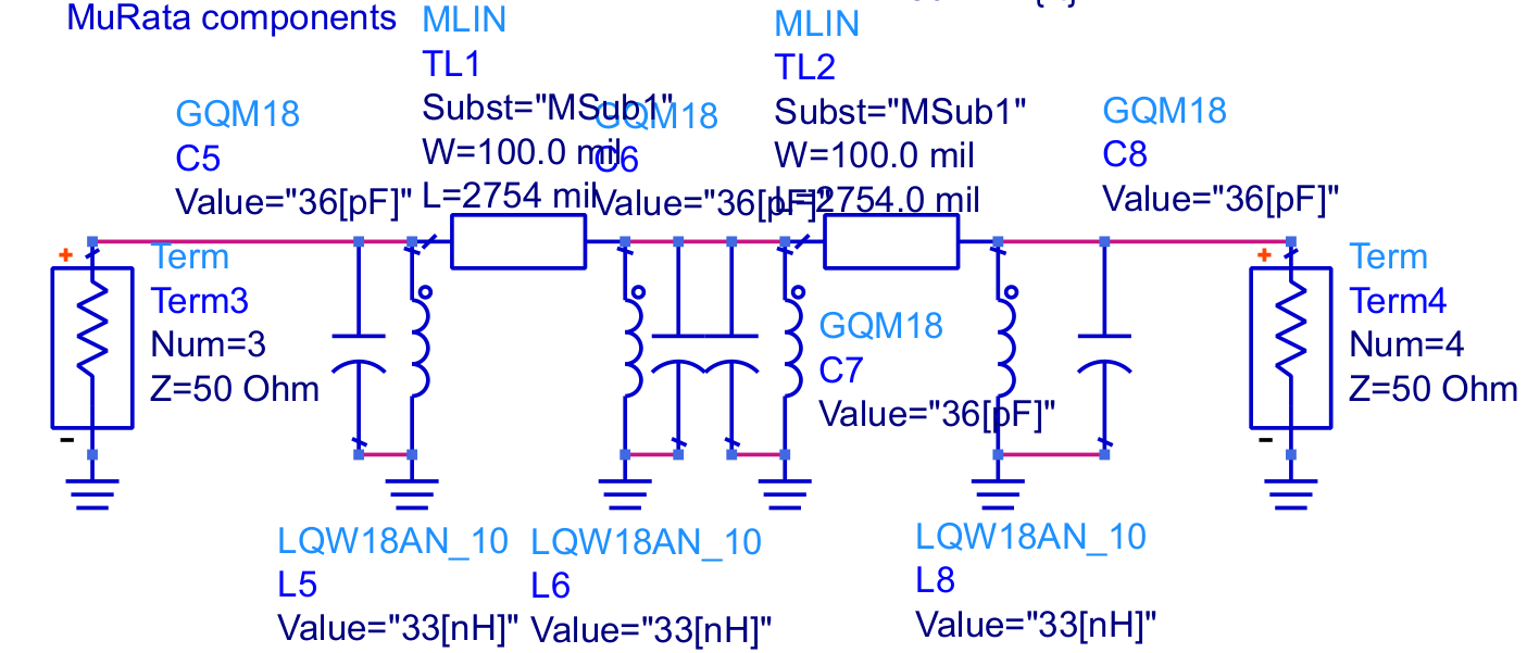
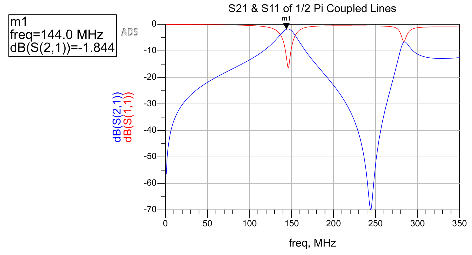
This circuit is then simulated in ADS. The behavior of the original coupled line filter is shown in Figure 6, and that of the reduced-size transmission line and lumped element filter is shown in Figure 7.
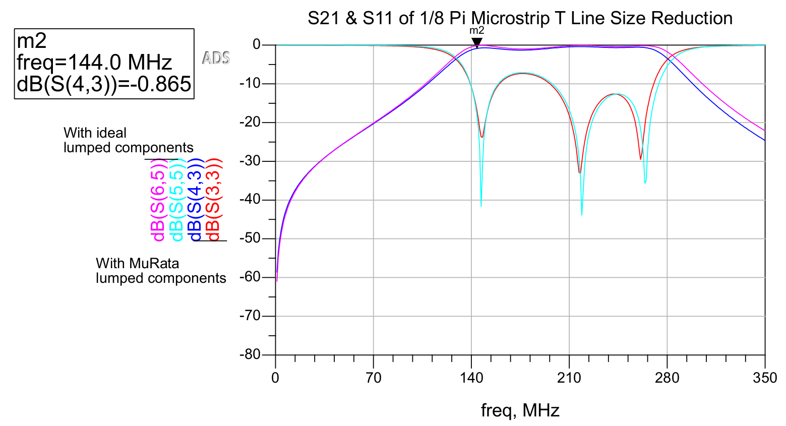
As is evident in Figure 7, the effects of using non-ideal lumped components are minimal, as opposed to the effects of non-ideal components in filters that make use of only lumped components. Transmission line filters with lumped components can be advantageous in attaining both a favorable match (due to resonance) as well as a low insertion loss in the passband.
Interestingly, the resulting passband is far wider in the transmission line filter. This could likely be remedied by adding more elements and through further tuning, or by investigating the cascaded impact of the fractional bandwidth used to derive the even and odd characteristics of the original coupled line filter. It is also possible that resonant characteristics of the transmission lines produces this effect.
As far as size reduction, each of the two coupled line pairs in the original filter is approximately 11.3 inches in length, while the transmission line segments in the new filter are only about 2.8 inches, and could be reduced further. Although the length of the transmission lines in the resulting filter can theoretically be arbitrarily defined, performance is impacted when this value becomes excessively small.
This approach for designing VHF bandpass filters is convenient in allowing the low-insertion loss of transmission line filters to be achieved in the small footprint of lumped-element filters, while also obtaining the favorable return loss and tight passband that resonant LC circuits can provide.
References
[1] Kang, I., Xu, H., & National Korea Maritime University. (2007, May 8). An extremely miniaturized microstrip bandpass filter. Microwave Journal. https://www.microwavejournal.com/articles/4775-an-extremely-miniaturized-microstrip-bandpass-filter
[2] M, Abhinaya, B, B., Dashora, H., & Kumar, J. (2020). Design and implementation of coupled line bandpass filter at c-band. AIJR Preprints. https://doi.org/10.21467/preprints.232